 Orlando, Florida, United States
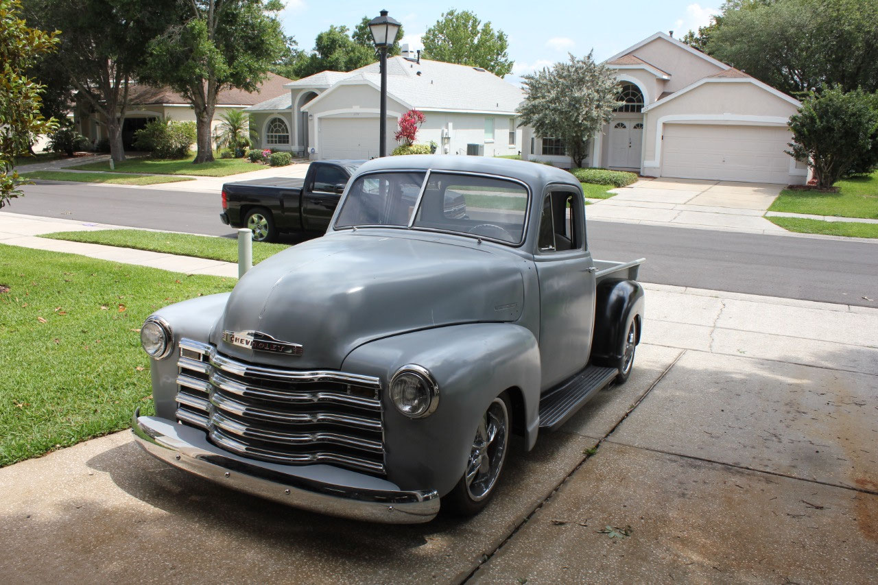
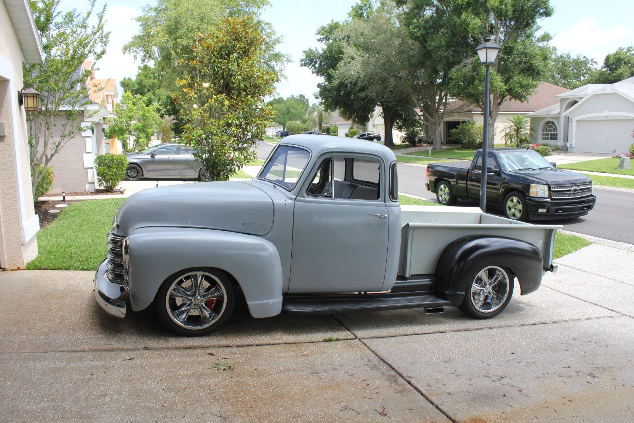
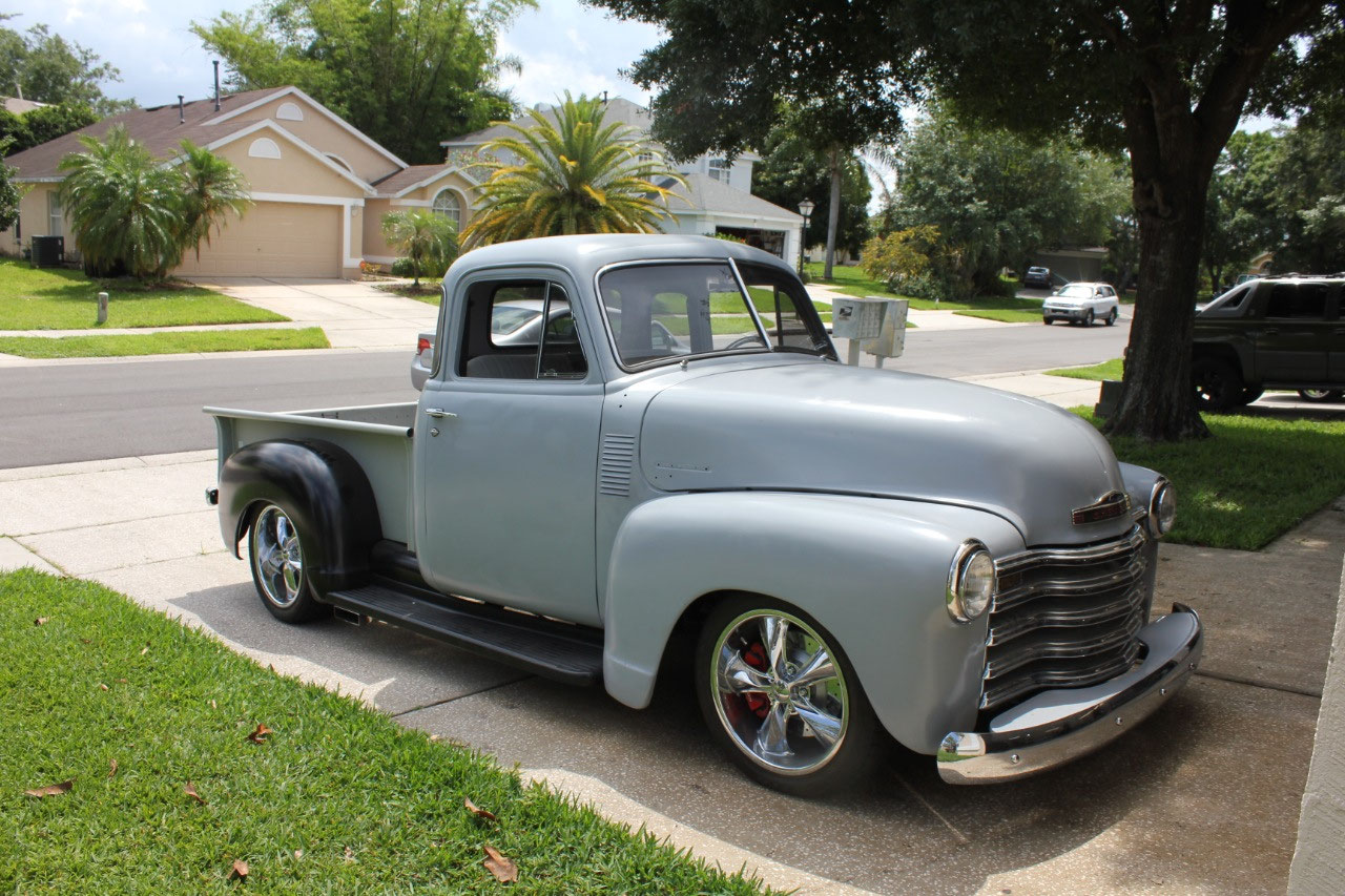
Now that the truck has become reasonably complete, I have
taken to driving it around the neighborhood occasionally to test the
drivability. It mostly drives pretty
well, but the first problem that I really didn’t like was the brakes. The pedal is just too hard, and there is very
little pedal travel. After a little
research, I realized that I didn’t know much about automotive break
design. It turns out, that the original
master cylinder I bought was a 1” diameter bore, and when I had a problem with
it leaking, I thought I was being clever by replacing it with a 1.125 diameter
bore. This was exactly the wrong thing
to do. The larger the bore, the MORE
pedal pressure, and the LESS pedal travel.
It turns out the original C4/C5 Corvette has a 7/8’ master cylinder, so
I should have chosen a smaller rather than larger bore.
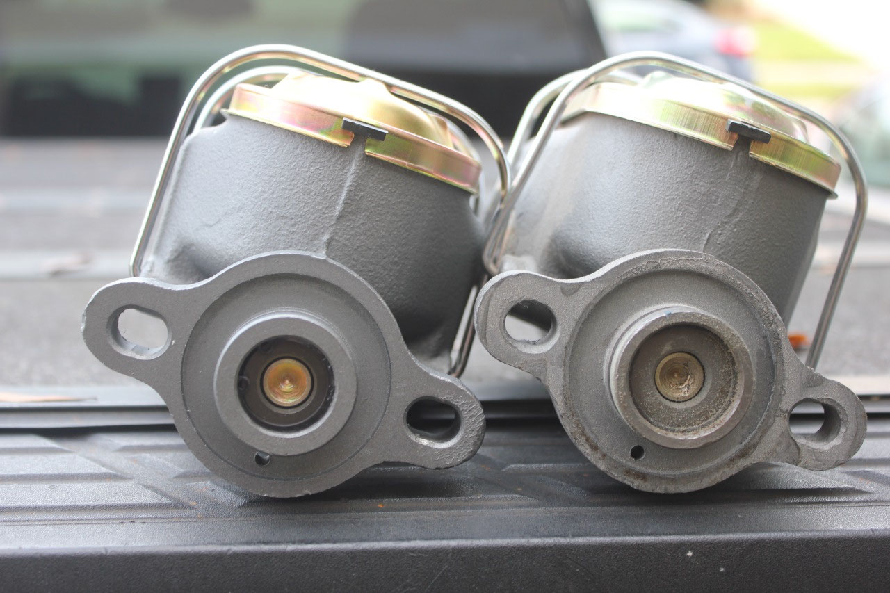
So I ordered a 15/16” bore configuration of the same master
cylinder, installed it and sure enough it was exactly what I wanted: LESS pedal pressure, and MORE pedal
travel.
The brakes work great now and
are exactly how they should be. I also
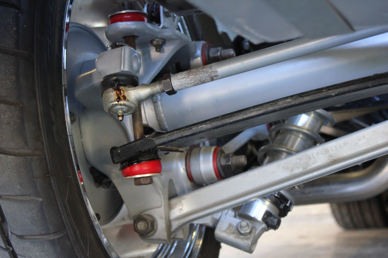
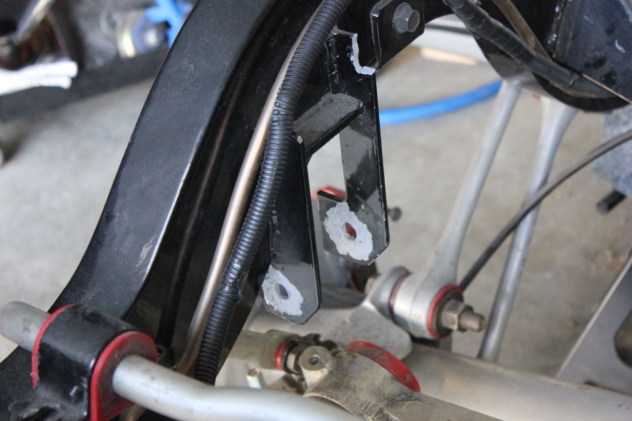
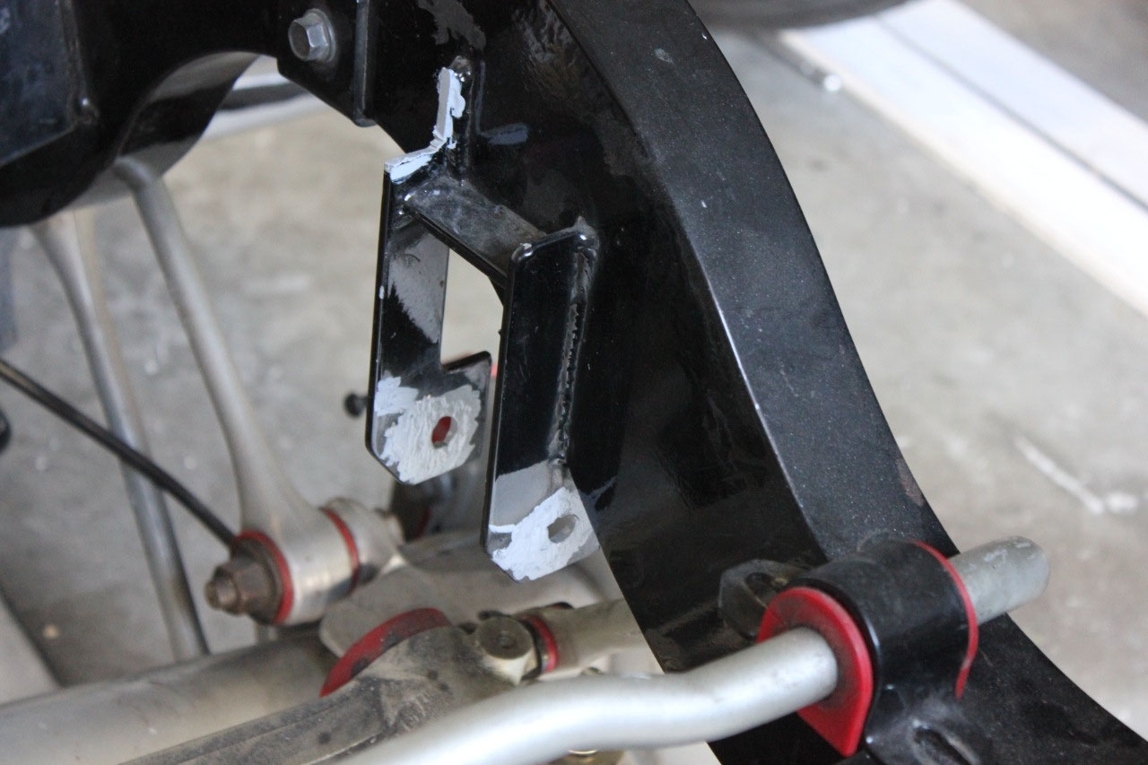
encountered a problem while turning at the end of the driveway. It turned out that there was a position of
turning and front suspension travel where the front sway bay would interfere
with the front steering rack causing the steering to bind.
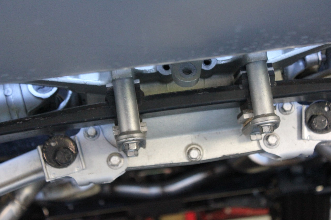
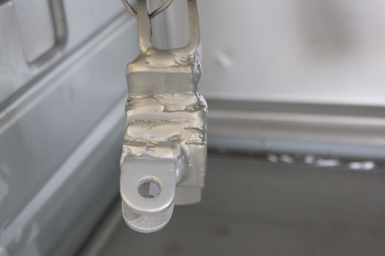
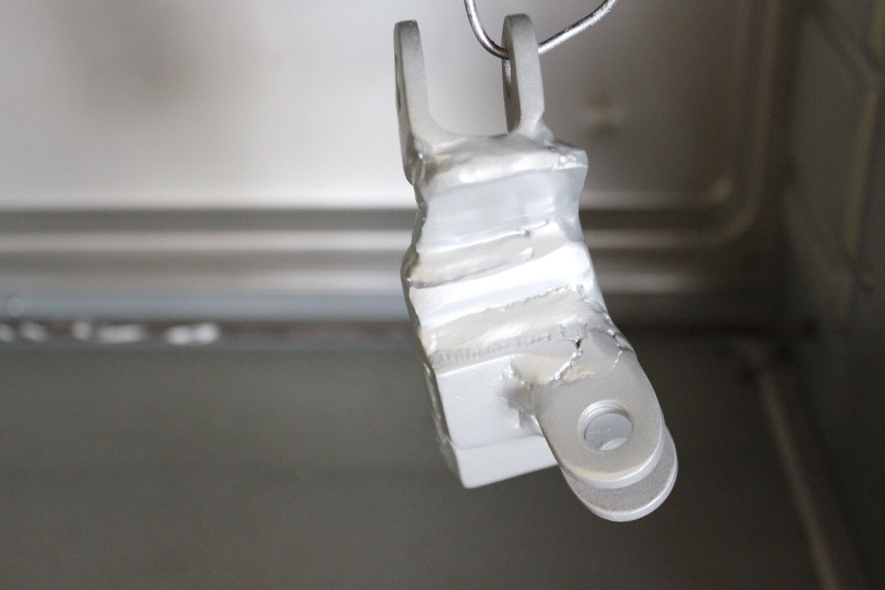
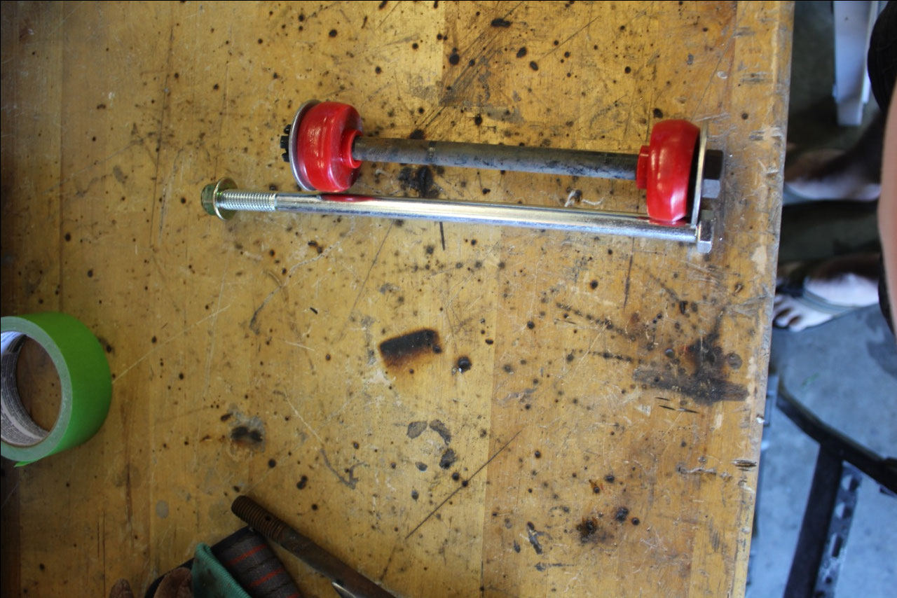
Investigation of the front sway bar found that I needed to
extend the length of the front sway bar link by about an inch, which was not
too difficult, but it meant that I needed to change the angle of the fabricated
mounting flange that attached to the lower control arm. Fortunately a little quick work with the
welder, and the problem was solved!
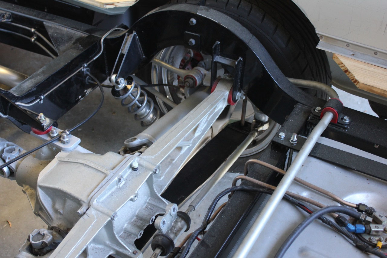
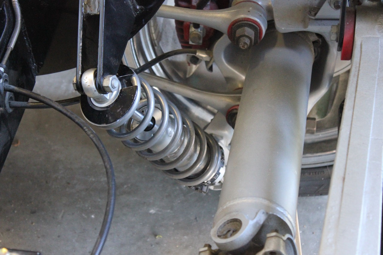
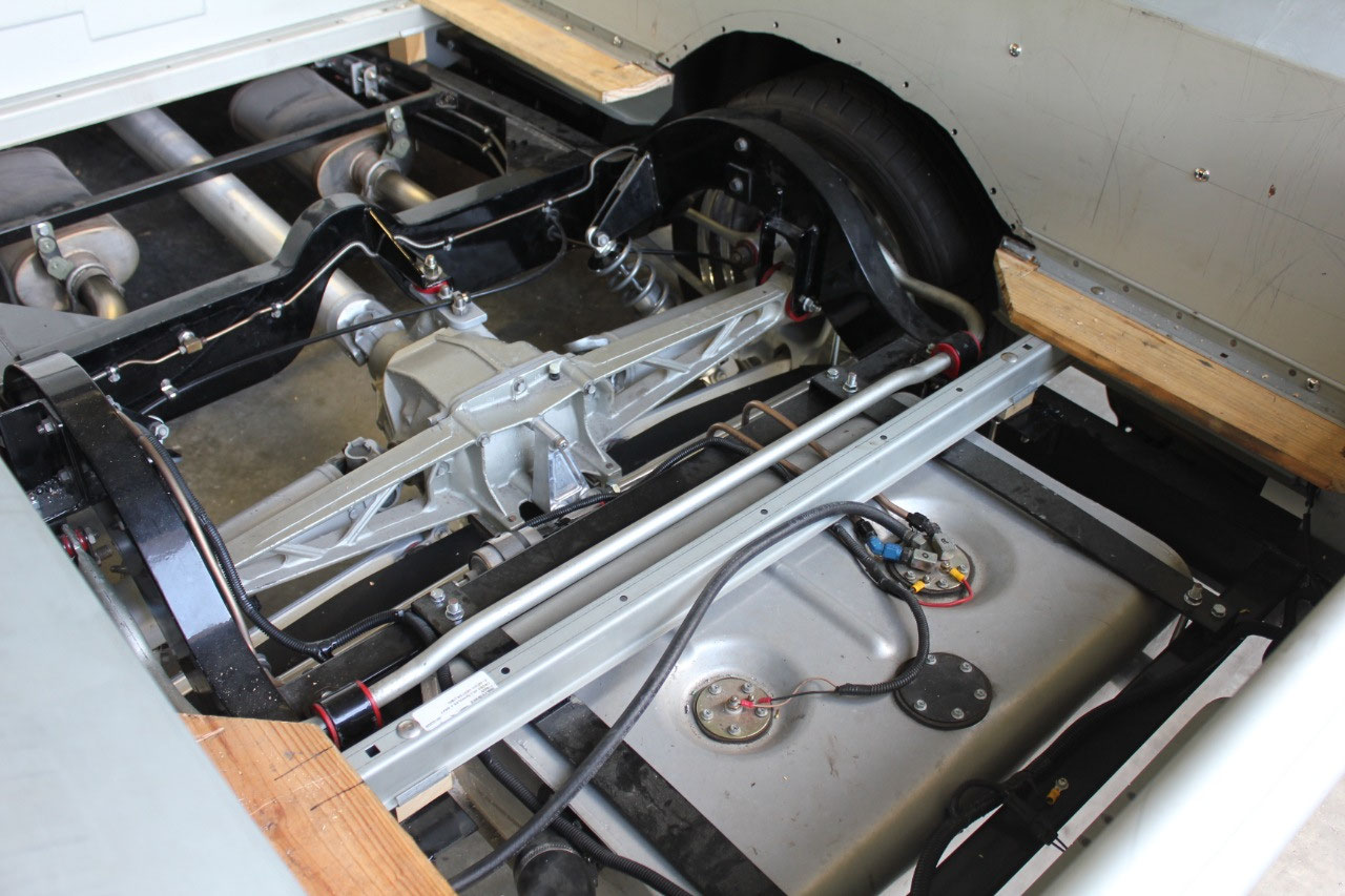
This was also time to take another look at the rear
springs. After looking at several
solutions involving relocation of the coilovers, I decided it would just be
easier to use the original Corvette transverse leaf spring for the main support
and use the coilovers for as some minora augmentation, and as a shock
absorber. Unfortunately, I had somehow
thrown away the original Corvette leaf spring during an overambitious garage
cleanup, so I had to order a replacement on eBay.
I just had to make sure I selected one of the
softer versions. Luckily I still had
most of the other hardware, though I was missing one of the shims. I also bought a lowering kit, which is
essentially just a couple of longer spring bolts that allows me to easily set
the ride height. I replaced the coilover
springs back to the original 175 lb/in and the height looks great.
The only problem with using the Corvette leaf is that the
toe rod flip kit that I had installed when I first mounted the rear suspension
would no longer fit. Fortunately Flat
Out Engineering, makers of the original toe rod flip kit had a new version
available that works with the Corvette leaf.
The rear suspension is finally finished assembly and the height is
great!
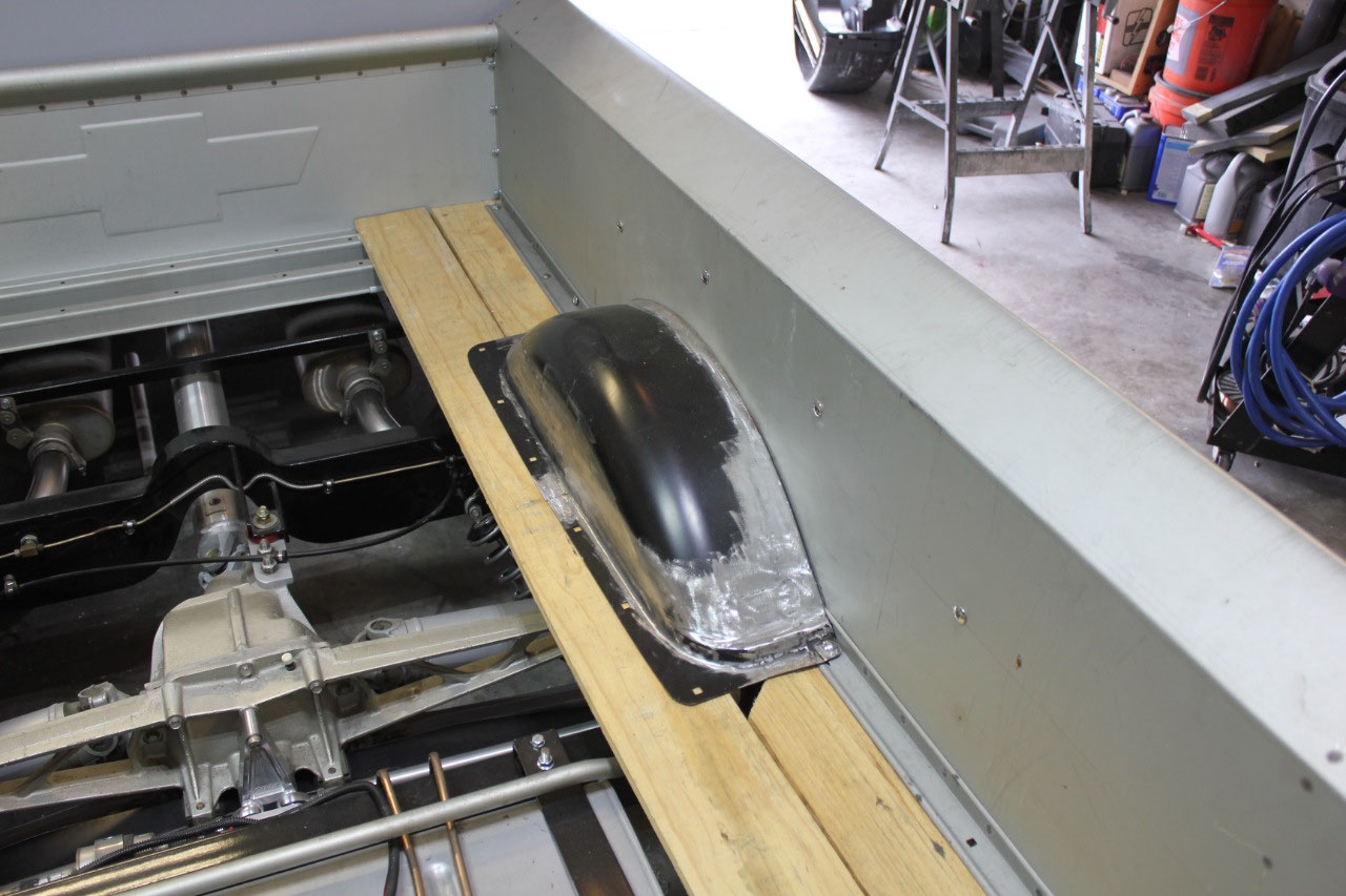
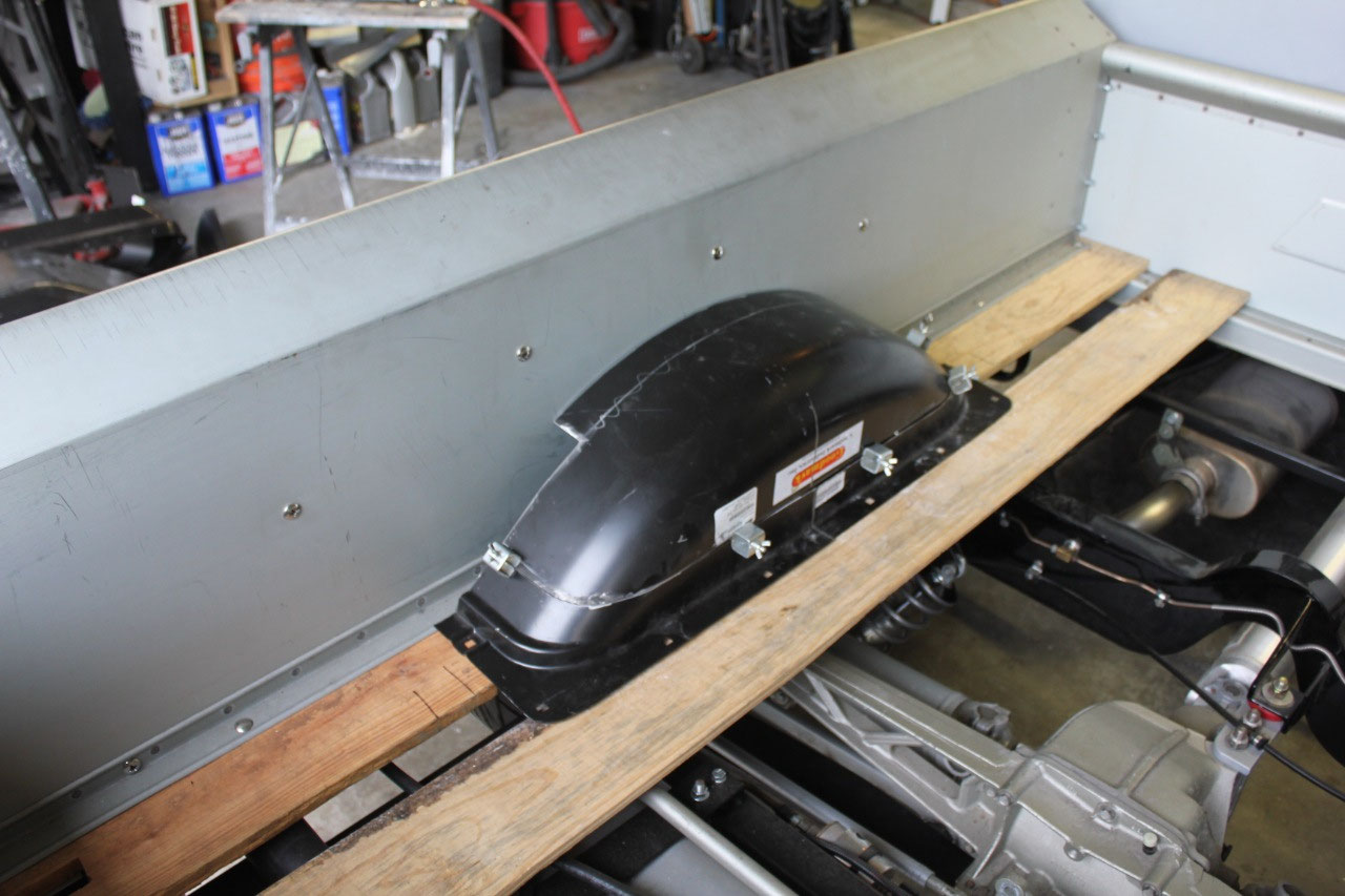
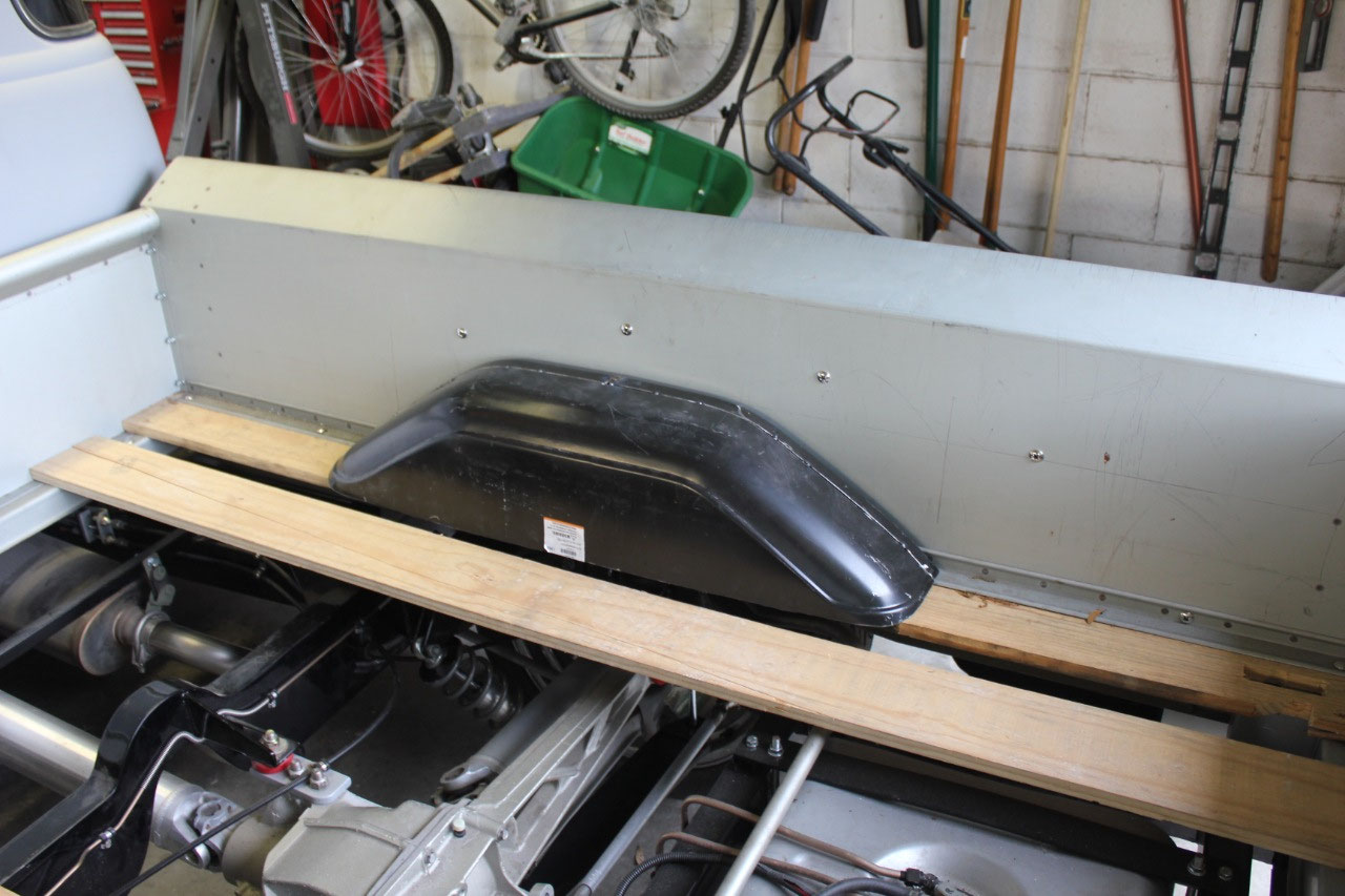
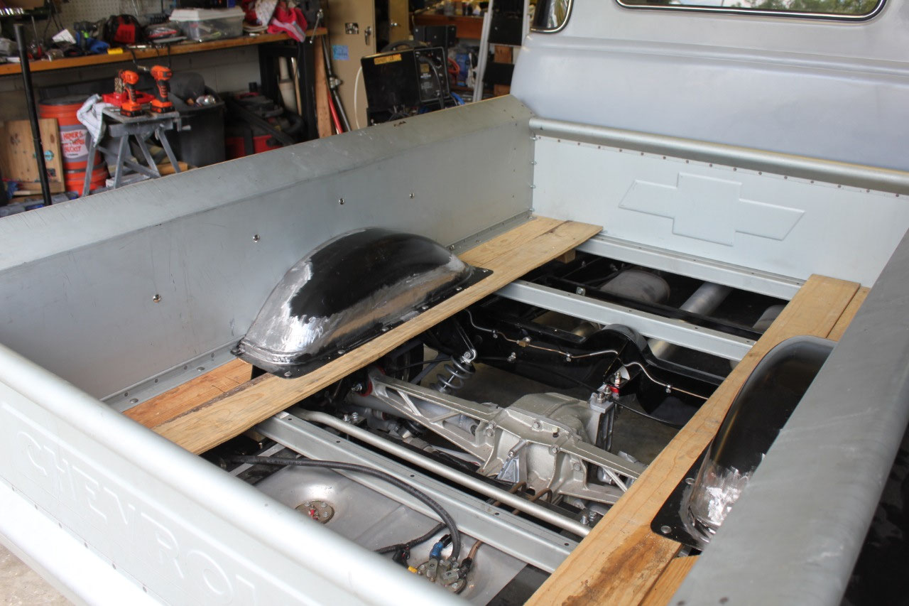
Now that my suspension problems are resolved, it’s time to
tackle the most difficult fabrication task to date. I have looked everywhere for wheel tubs to
fit inside the bed. There are a couple
designed for this truck, but they are typically only a couple of inches deep
for tire interference with the bed sides, but are tall to accommodate lowering
with air-ride.
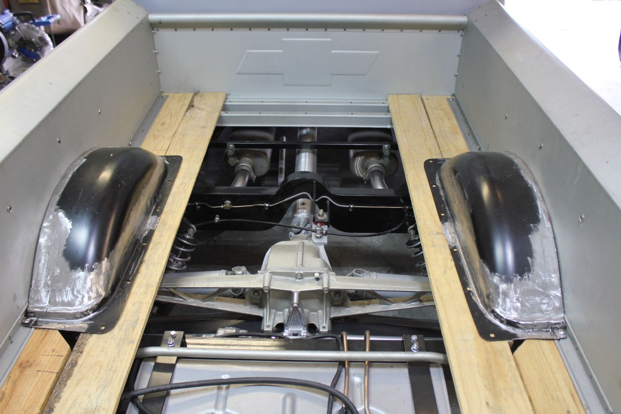
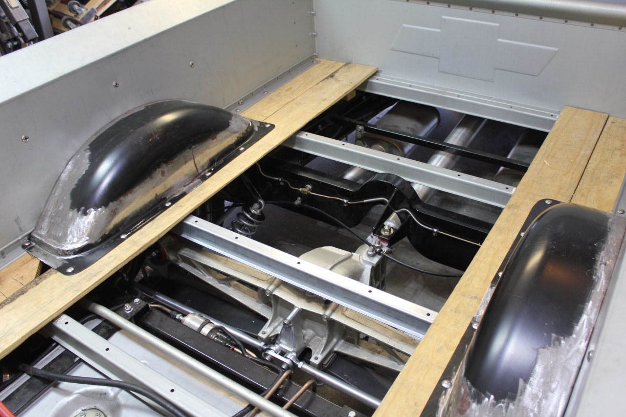
The problem with my
truck, is that even though I only need a couple of inches width for tire
clearance, I need a full 7” for frame clearance as the frame kick-up for the
Corvette rear suspension intrudes into the bed about 7”. With a wheel tub that wide, I am trying to
minimize the height so it won’t look overly large. Since I am not using air-ride, a height of 8”
should be sufficient.
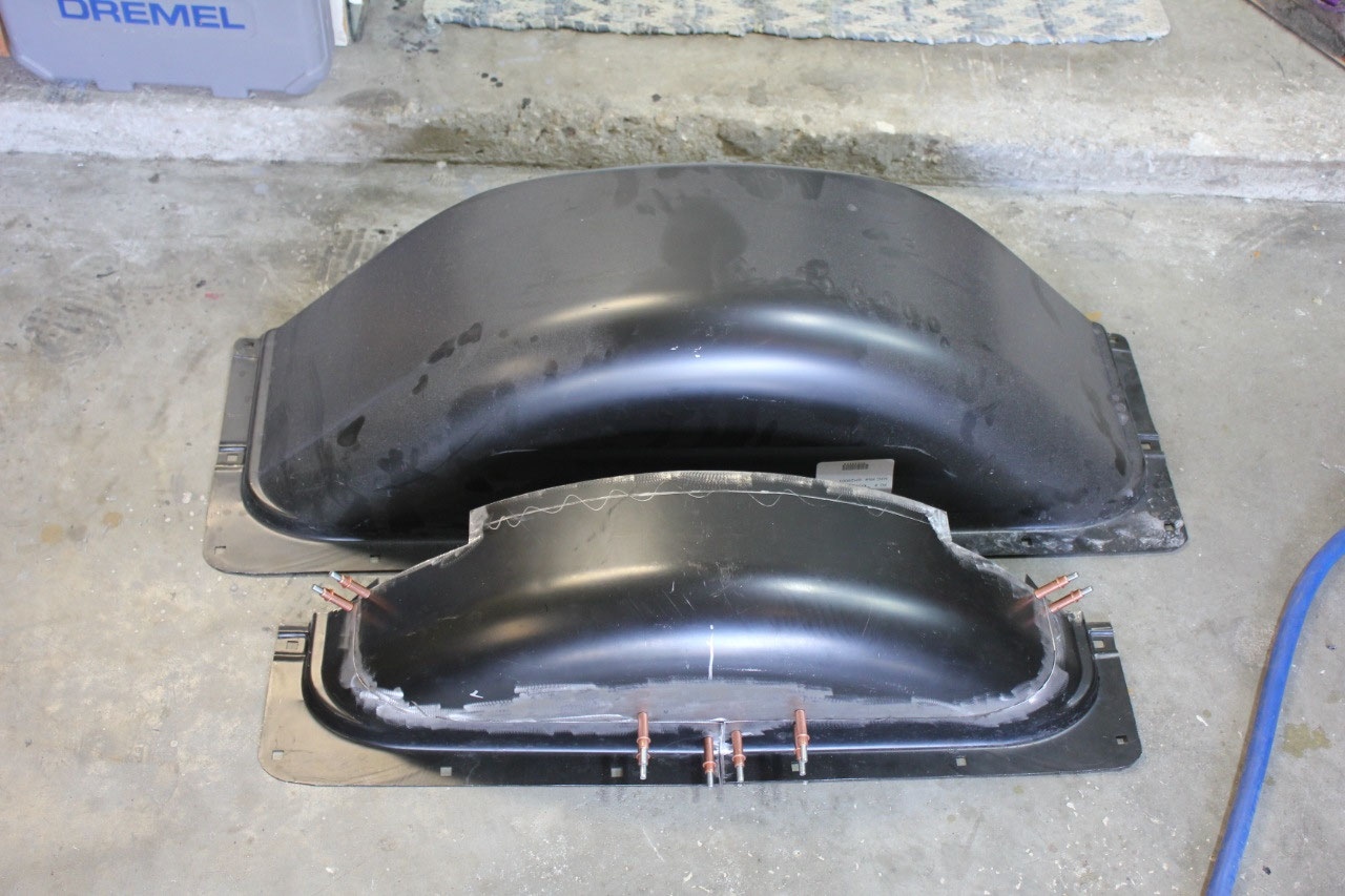
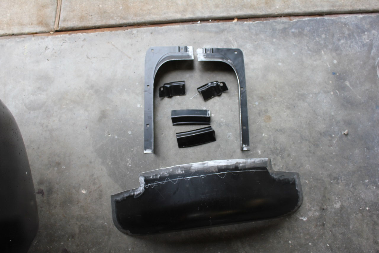
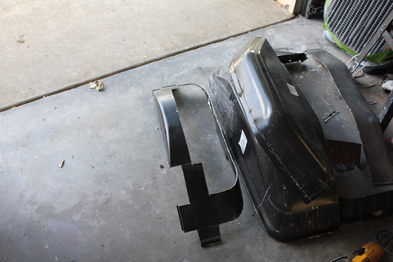
After looking at many design styles, I decided on either
60-66 Chevy Styleside pickup or 70-78 Chevy Blazer. The 60-66 Chevy were rounder and had the
correct style mounting flange, and the Blazer was more rectangular. Both were MUCH too large, at about 11” tall
and 12” wide. The plan was to section
each of the wheel tubs and weld them back together in a smaller
configuration. I would use the mounting
flanges from the 60-66 Chevy and the upper portion from whichever one looked
better.
I cut the upper portion of each one down and tacked it back
together to see what I was working with, and quickly discovered that the 60-66
Chevy was 16 gauge steel and the Blazer was 18 gauge.
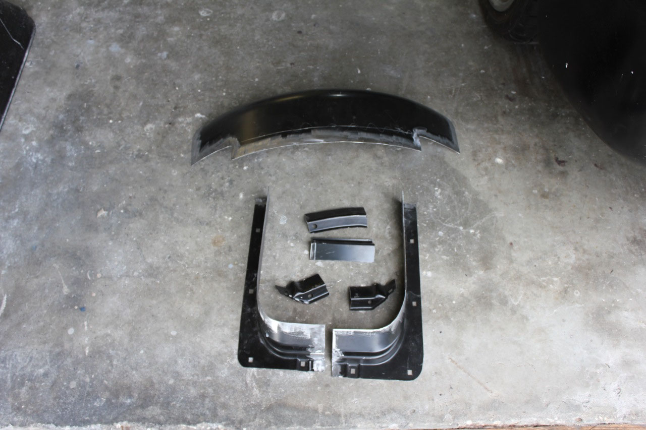
In this application, the 16 gauge was just so
much better to work with, that I decided that even though I liked the
rectangular look of the Blazer, the 60-66 Chevy would be stronger and much
easier to work with. In looking back, I
now think the 60-66 Chevy looks better too.
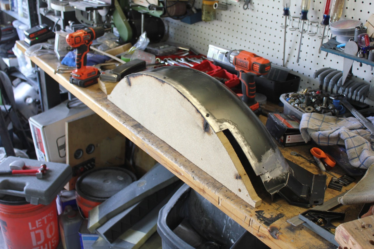
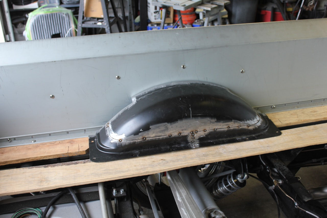
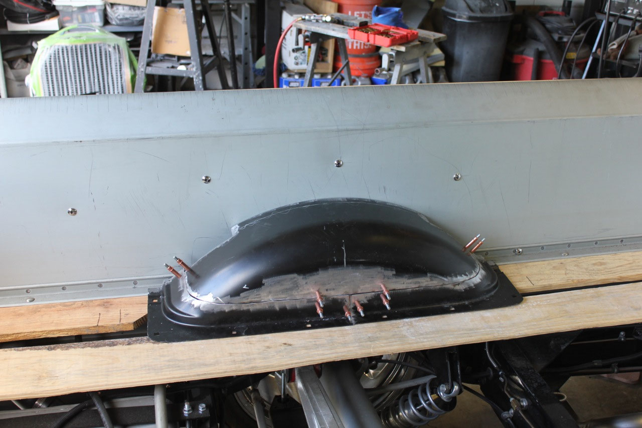
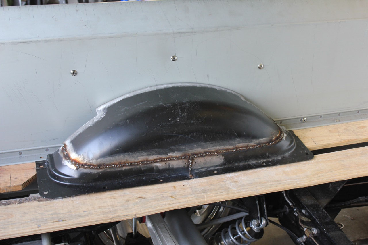
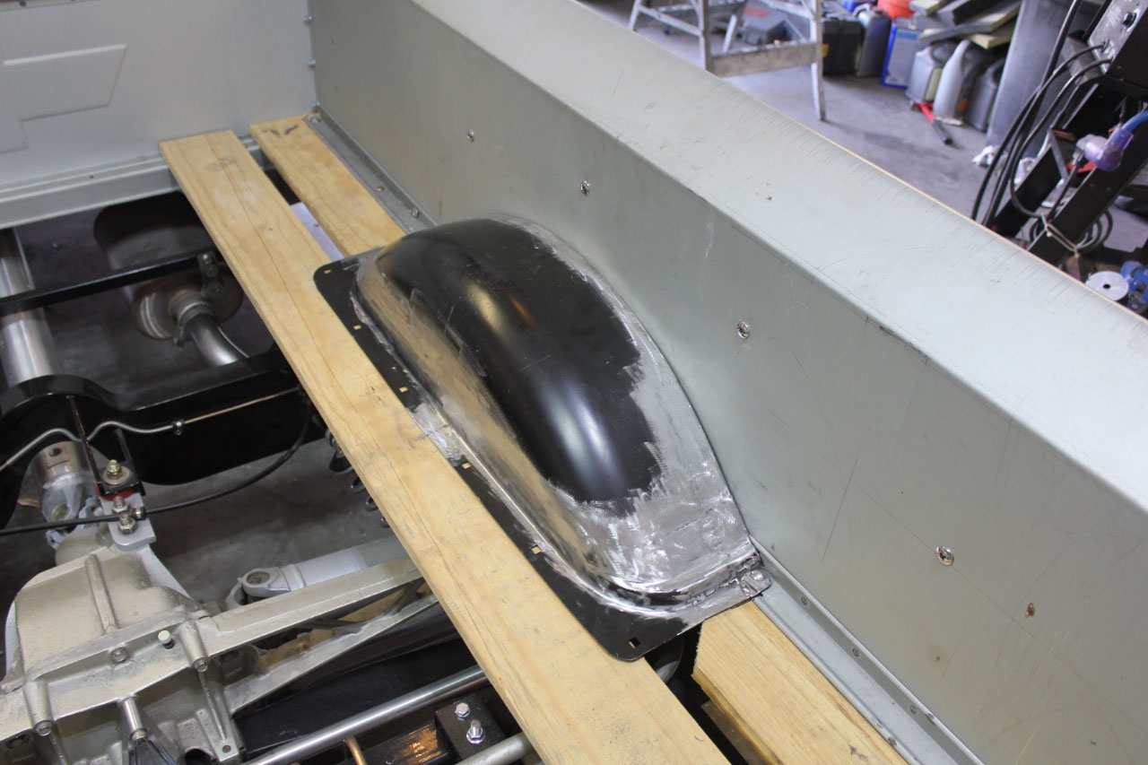
This is a complicated cutting task as all of the sides of
the wheel tubs are complex curves. So I
tried to cut where the surfaces were flat and reassembled the first side using
metal strips and Cleco fasteners. I then
used the pieces of the first to mark and cut the second, then trimmed the
second piece so that it would fit in the first wheel tub. I did this for each of the 3 main pieces so
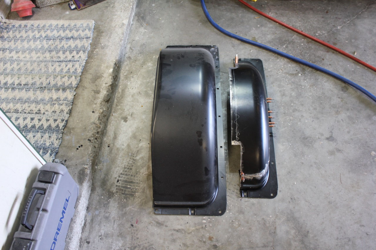
that I would be sure that both wheel tubs were exactly the same size. Somehow it worked! A year ago, I would not have had the skill to
do this, but I have improved over these last few years, so that even after
welding all the pieces together I have 2 wheel tubs that are almost exactly
identical.
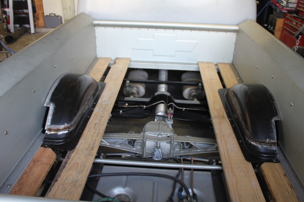
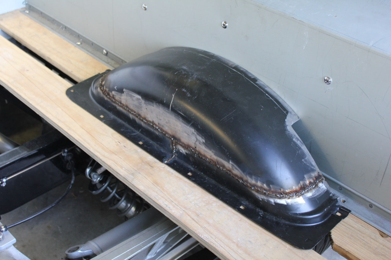
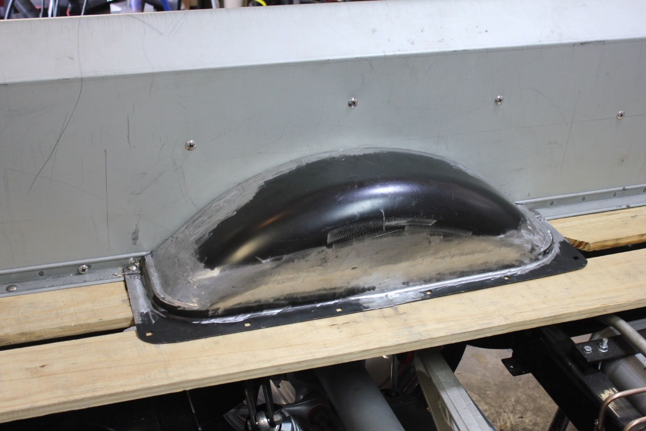
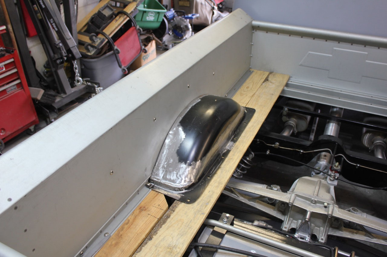
I finished up the mounting flange where they attach to the
bed sides using the same wood template for both sides to ensure the same
curvature.
It did take a little grinding
and filing to get the wheel tubs to fit at the bed angles, but all they need
now is a little bodywork and primer, and they will look t\like they were made
at the factory.
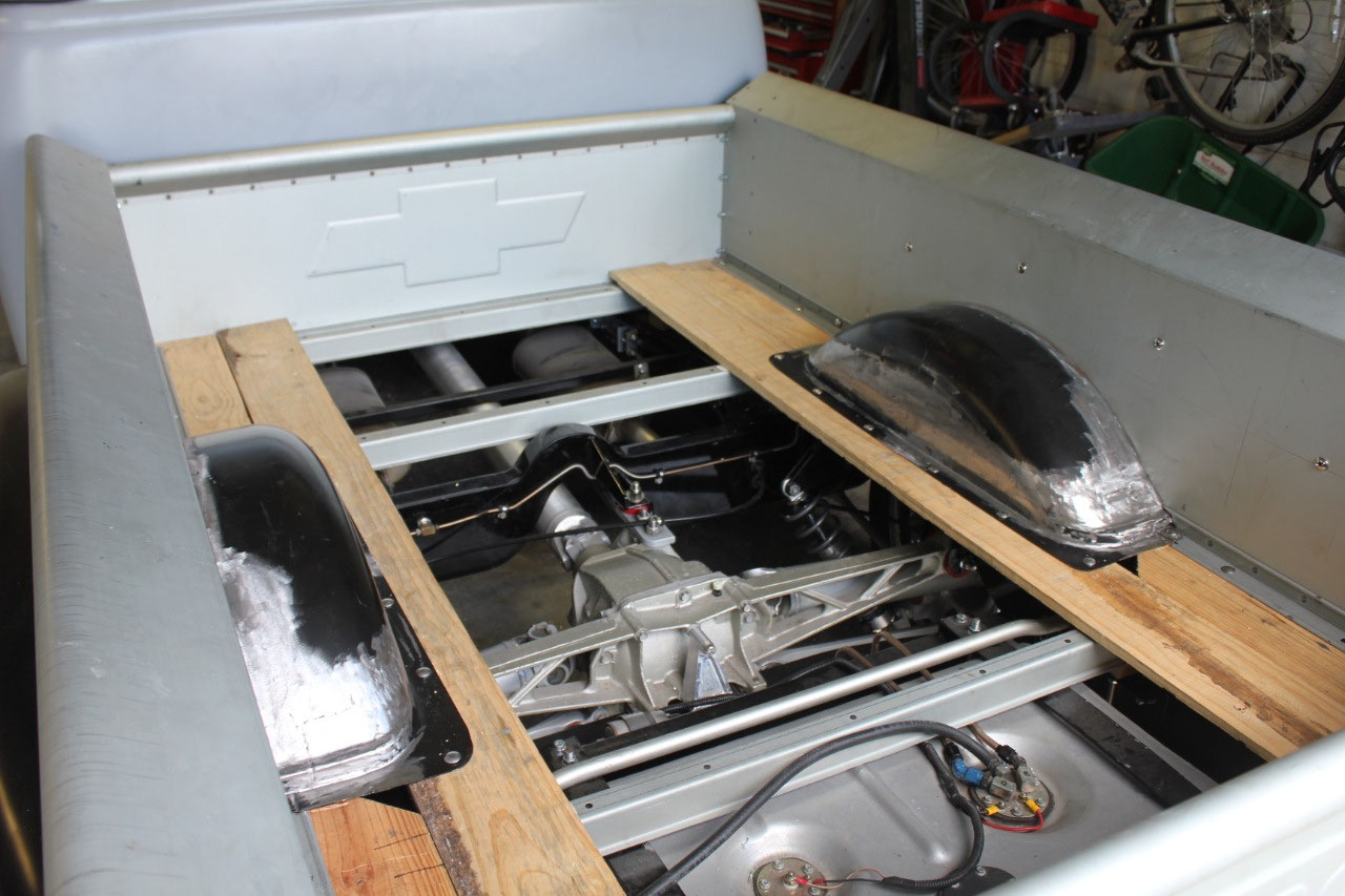
Now that the wheel tubs are complete, it’s time to tackle
the last of the wiring. I’m trying to
keep the wiring connectorized in such a way that the bed can be removed without
cutting any wires. I did have to remove
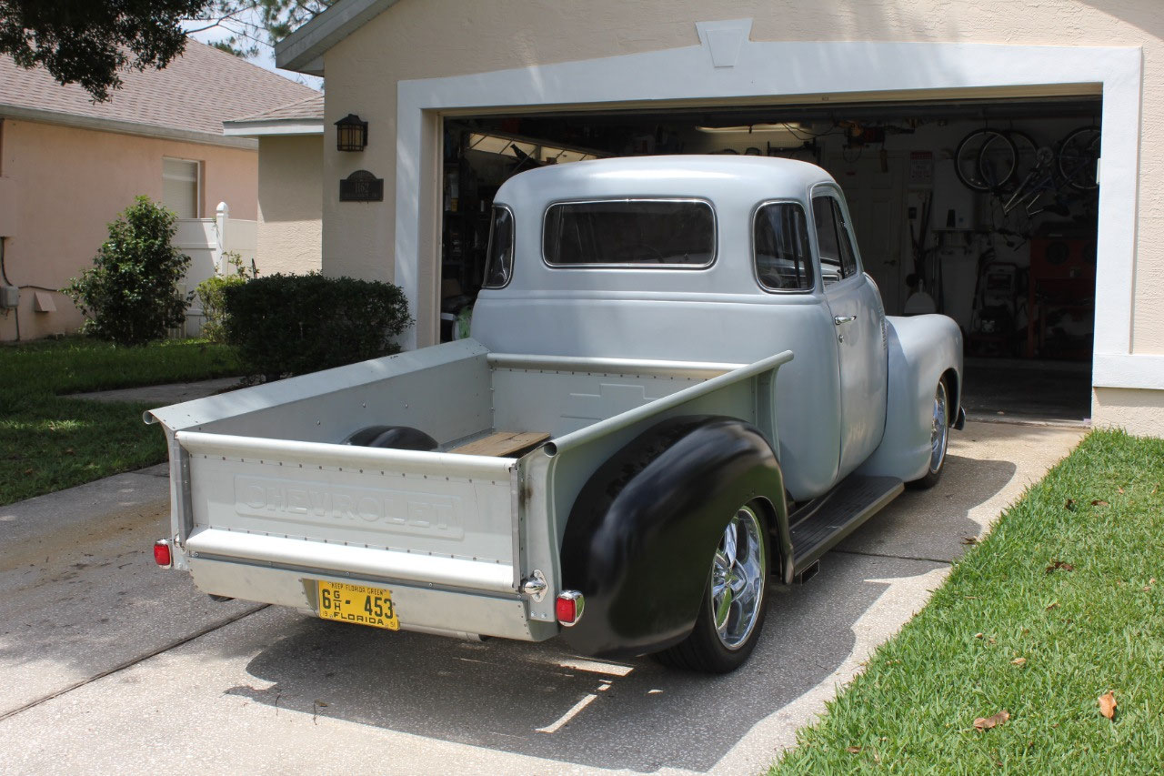
the rear roll pan to cut in a license plate light above the license plate. While the roll pan was removed, I also
drilled additional holes for the license plate that would fit the original 1951
Florida tag. It turns out the hole
spacing on the 1951 tag is different from modern tags and I wanted to be able
to accommodate both. I was not able to
install the backup lights which will be round LEDs that fit in the round
openings at the end of the bed sides. I
installed the connectors into the harness, but I need to drill holes in the
rear cross sills to pass the wires through.
This will be much easier when I disassemble the bed for primer and the
rear cross sill is loose on the bench.
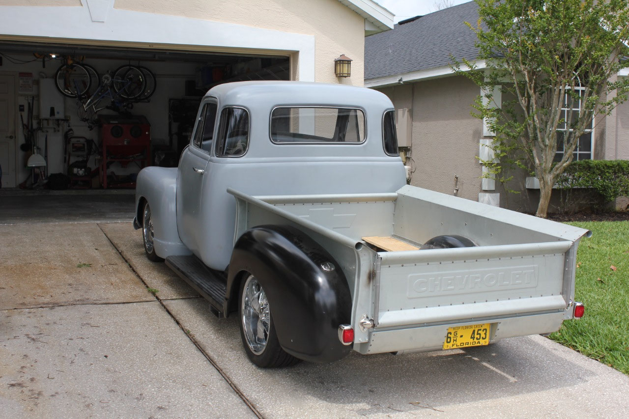
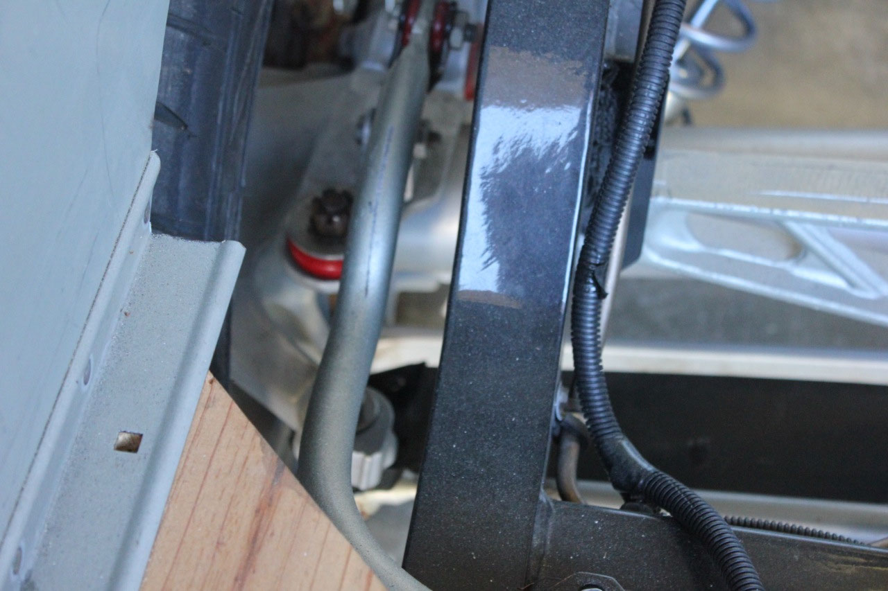
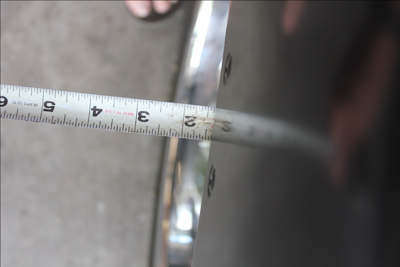
Now that everything was fully assembled at the rear, and it
was time to stand back and admire my handiwork, I noticed that there appeared
to be a problem with tire clearance and the rear fenders. While neither rear tire rubbed on the fender,
one side seemed much closer to the fender lip than the other. Sure enough, a measurement from the tire to
the fender lip on the driver’s side was 1-1/4” and on the passenger’s side was
2”. This is a ¾” difference, and it was
noticeable!
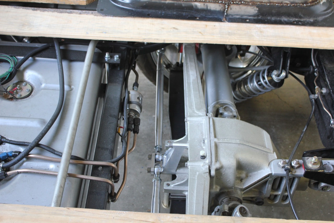
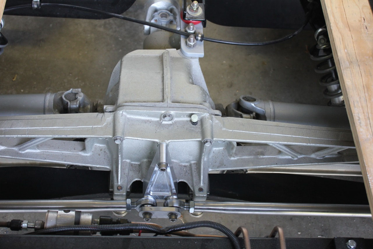
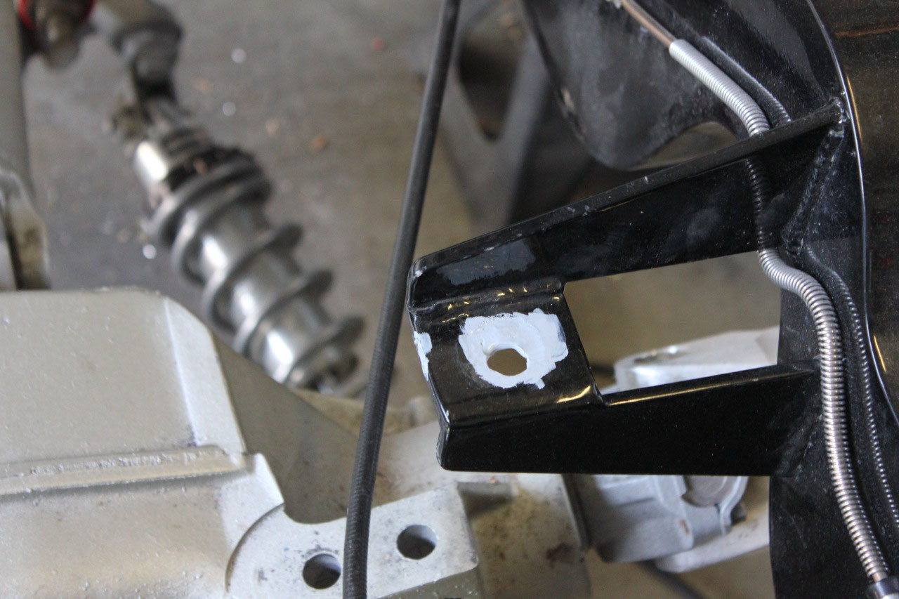
After making several measurements of the frame and the bed,
it was apparent that the problem was in the frame. The mounting points for the Corvette rear
suspension were not exactly centered in the frame. The frame to body measurements were good, but
the entire rear suspension needed to move to the right by 3/8”. What this really meant was that the holes in
“batwing” hangers on either side of the frame at the rear would need to move to
the right 3/8”, and the center mount would also need to move to the right by
3/8”. This meant the center mount adapter plate needed to be notched to provide
relief.
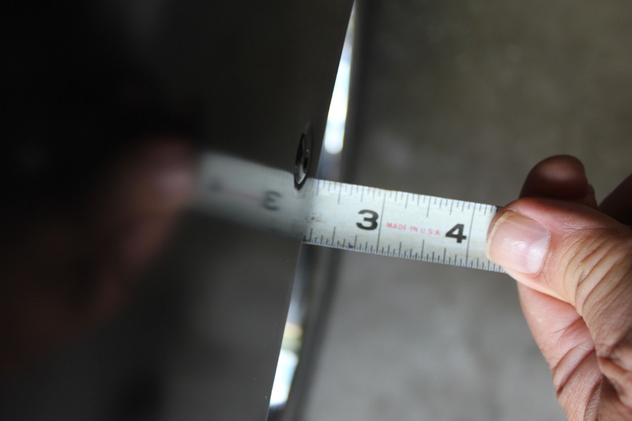
This was a tedious task, time consuming but not particularly
difficult. It meant drilling new ½”
holes 3/8” to the right of the old holes and welding up the old holes, grinding
everything smooth, priming, painting and reassembling. It took a few days to get everything right,
but it all looks like it was never modified except that the distance from the
tire to the fender lip is now 1-3/8” on each side! So for now it’s all back together, looks and
drives great, and the bed is ready to be disassembled and primed. In looking at the bed center cross sills, the
rear center cross sill is a little further back than stock, and the front
center cross sill is a little further forward than stock. This means that the
distance between the 2 center cross sills is just a little too wide and that it
would be better to add an additional cut down center cross sill, connected to
the wheel tub mounting flange for support.
So I ordered another center cross sill from Mar-K along with a few
goodies, and in the meantime I’ll take a look at the cab alignment.


2025-05-22