 Orlando, Florida, United States
With all the
miscellaneous rusty parts restored, it is finally time to do something really
fun. It’s time to design the under seat
electronics. As an electrical engineer,
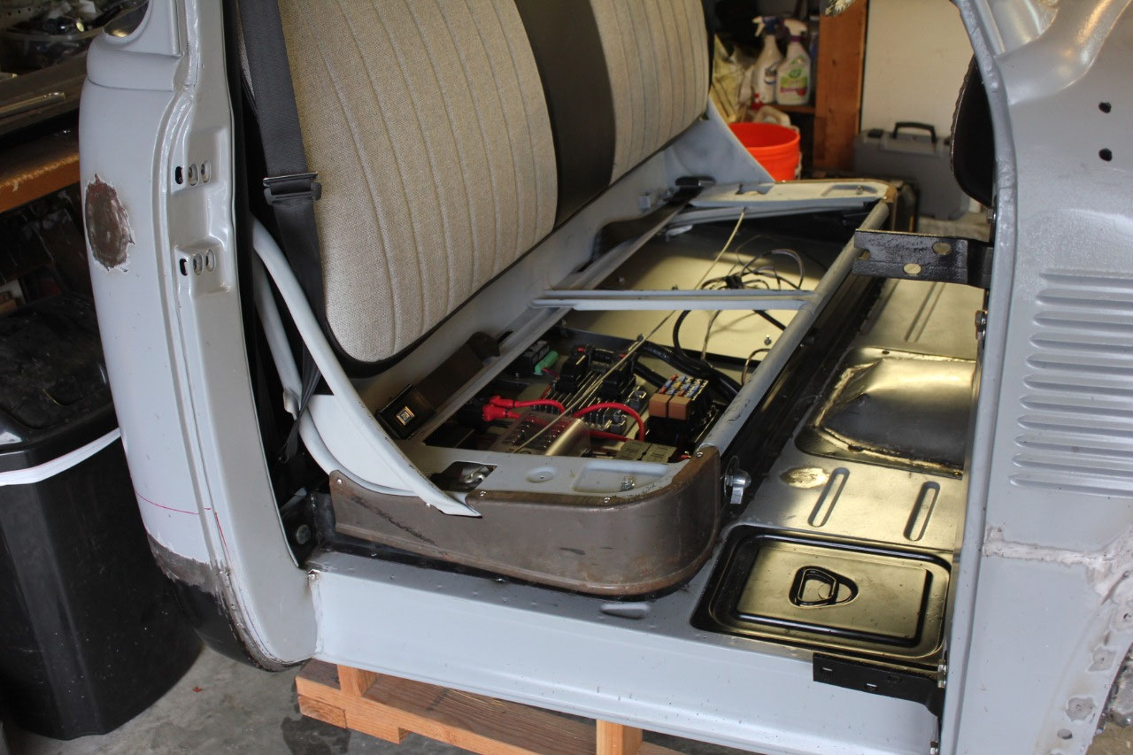
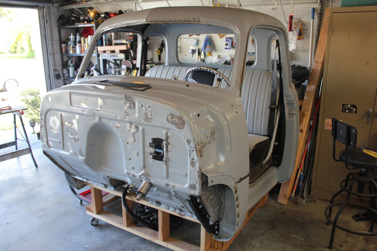
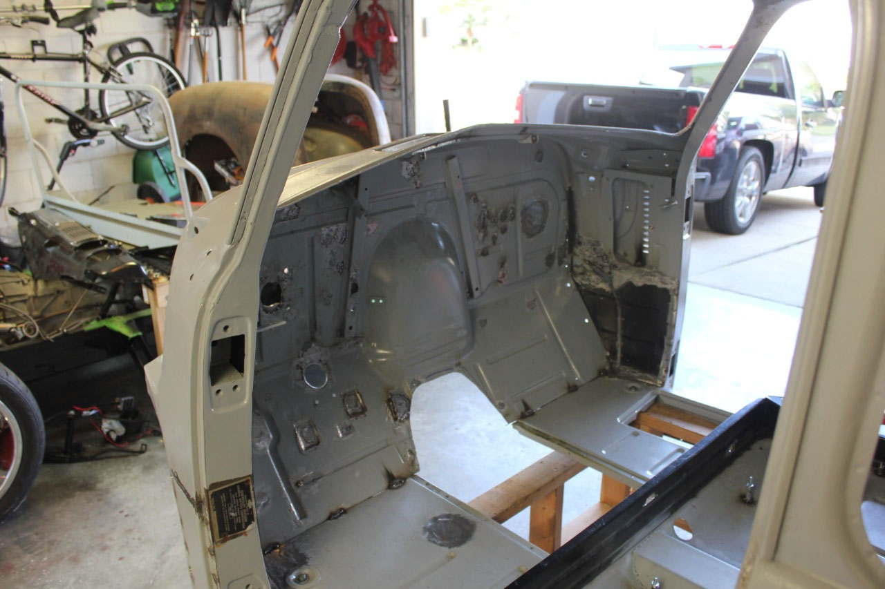
the electronic stuff is always the most fun, and the most comfortable. In this truck, the original design of the
seat includes a mounting platform with some underseat storage. The bottom cushion of the stock seat is
removable giving access to this storage area.
I never liked hanging all the various electronic modules and relays on
the inside firewall under the dash. It’s
too cluttered and is hard to access. The
storage area under the seat is perfect!
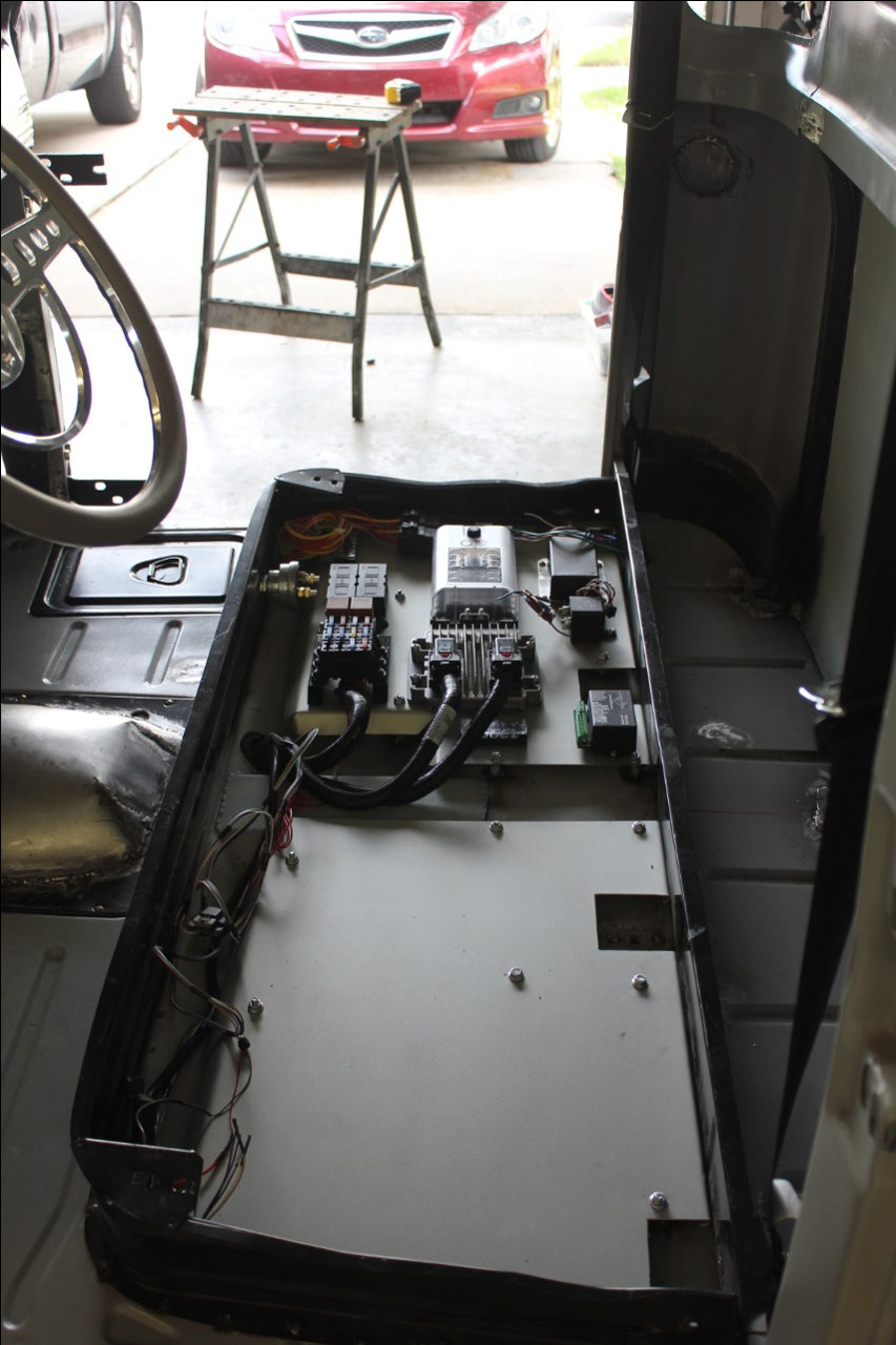
I didn’t want to
bolt things directly to the floor, mostly because I didn’t want a bunch of
bolts protruding through the floor, but also I wanted to allow for a gap below
the electronics in case some water got into the cab, it would short everything
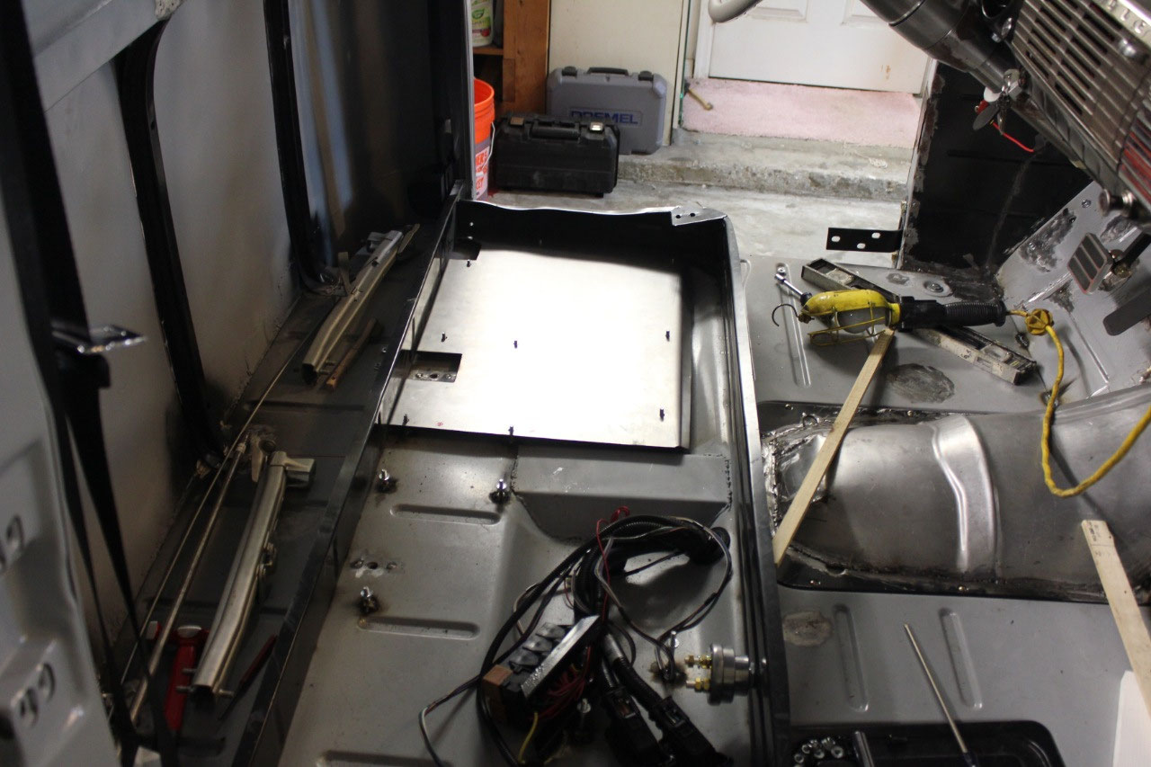
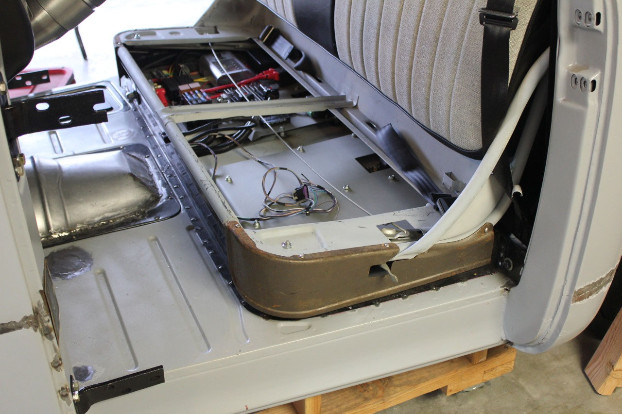
out. I decided to split the area below
the seat into 2 platforms, with the passenger side platform containing the bulk
of the engine controls and the driver’s side containing the controls for the
gauges, cruise control, alarm etc.
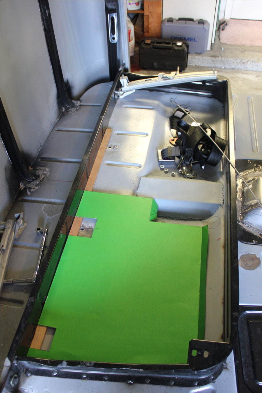
The first step was to create a cardboard template for the
area, then cut the platform out of 16 gauge steel. I then folded over the rear edge for strength
and folded the front edge down at an angle for both strength and for access to
the front wall of the underseat storage so I could drill through the front wall
and grommet the wires passing through to the engine.
The biggest limitation was the overall length
of the engine harness, which was longer than the original, but I had concerns
that it might be a little short for where I wanted to locate the ECU computer.
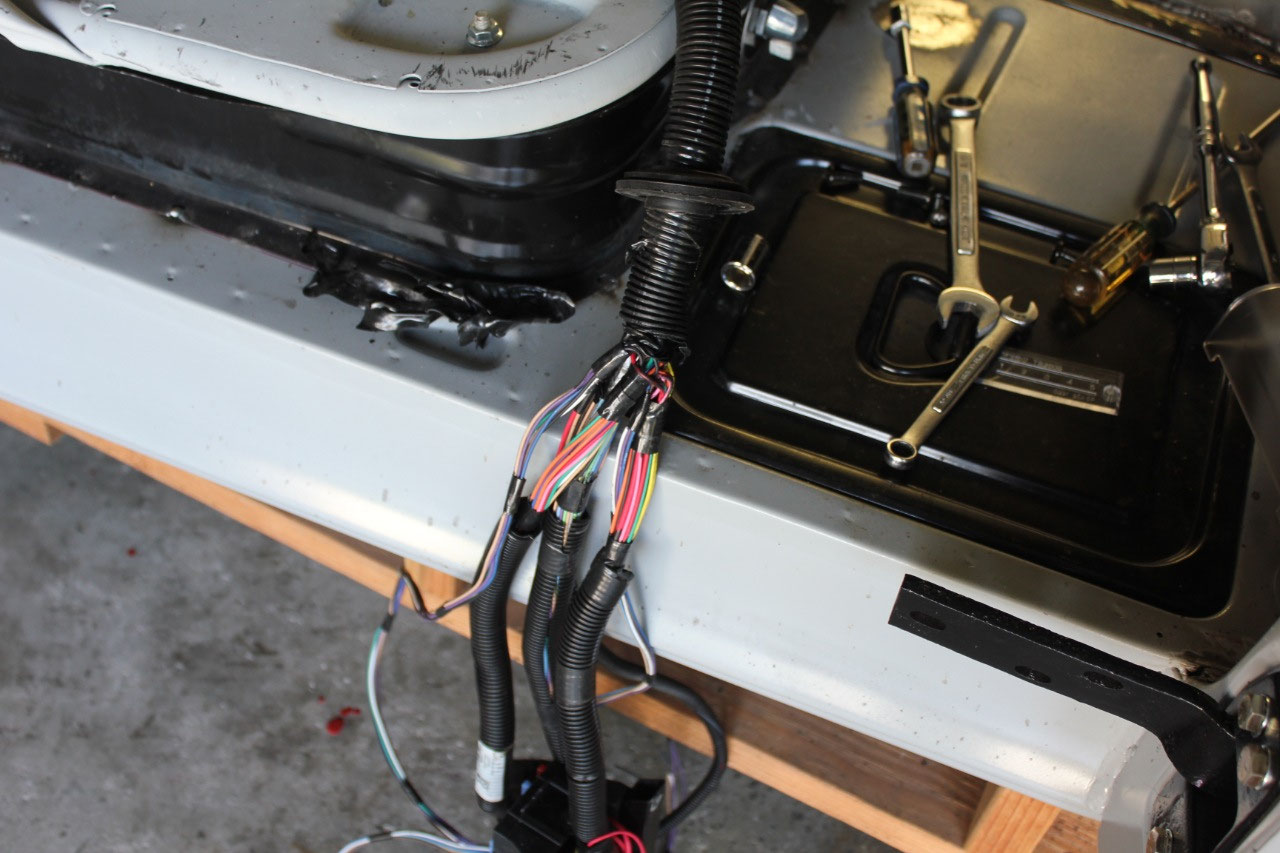
Since the engine harness was still connected to the engine
and chassis, I cleared off the storage table that I had built above the
chassis, and with some careful measurements, marked out the location of the
underseat storage area on the top of the table.
Now I knew the distances from the engine to under the seat and could see
if the harness would reach. According to
my measurements, it would be close, and maybe just a few inches short, but I
would deal with that later.
I was looking for a fuse box for under the seat, that could
accommodate all the circuits I needed and finally located one on Amazon that
had exactly what I wanted and was configured as 2 separate busses so I could
set up one side of the fuse box as +12V Battery Power, and the other side as
+12V Switched Power. With a 150A power
relay between the 2 busses, turning the key to the on position would only need
to turn on the power relay to turn on the Switched Power.
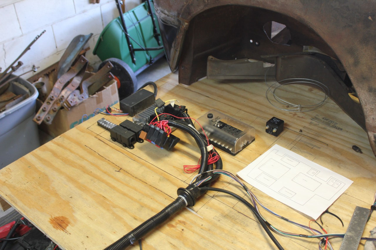
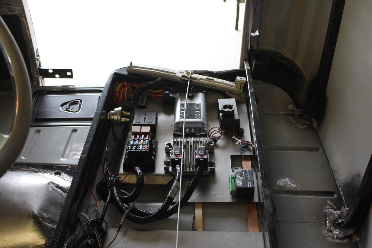
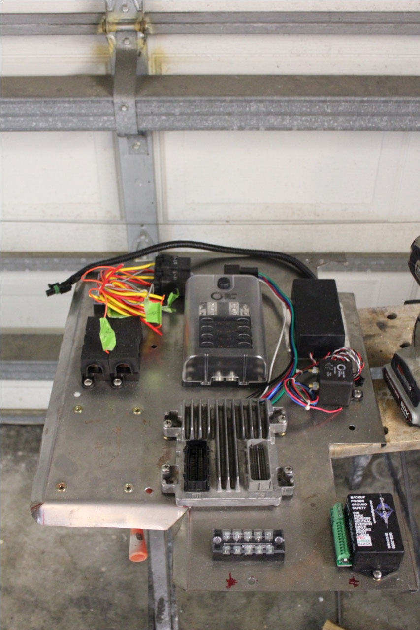
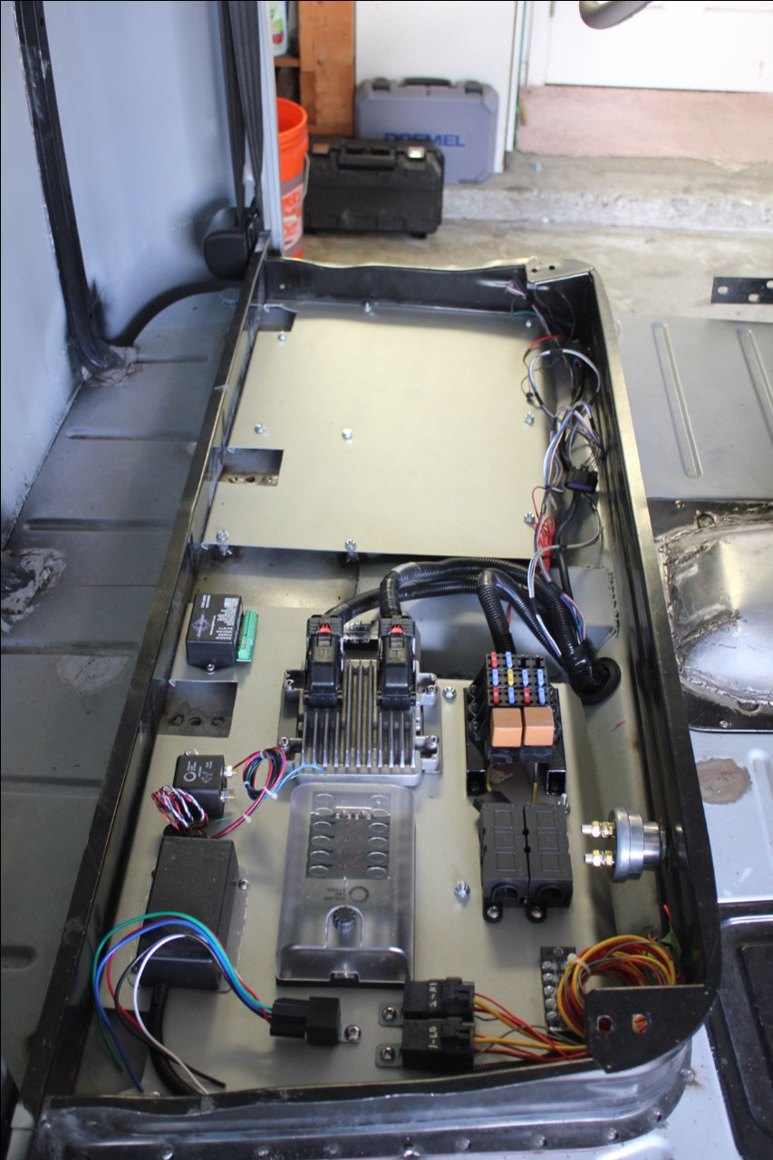
So I laid out the ECU, the engine harness relay and fuse
panel, my new fuse box, power relay, along with a couple of fan relays to run
the high/low speed radiator fan. Everything
fit well, with a little extra space still available, so I added the control
module for the eStopp parking brake. By
now, it was time to decide what to do about a neutral safety switch. I had originally decided to use the Lokar NSS
mounted to the transmission, but it didn’t have a bracket for the 6L80E, so I
would need to design one. In the
meantime, I had discovered that the Dakota Digital GSS-2000 gear indicator
would answer many of my problems.
I had already decided that I would be using Dakota Digital
VHX gauges, as I liked the look, and they also did not have any under dash
wiring. The gauge control module could
be mounted under the seat, and the only interface to the gauges would be a
simple Cat-5 cable between the control module and the gauges. The Dakota Digital GSS-2000, provides a
method of telling the VHX gauges what gear the transmission is in.
The interface is basically just a
potentiometer that is mounted on the side of the transmission with a rod
connecting the transmission selector to the pot. As the transmission selector is moved through
the gears, the pot is rotated and the GSS-2000 measures the value of the
pot. After a simple calibration, the
GSS-2000 now knows what gear the transmission is in. There is a single wire output of the GSS-2000
to the VHX gauge control box, and the VHX gauge will display the current gear
selection whenever the transmission selector is moved. In addition, there are outputs on the
GSS-2000 that enable a Neutral Safety Relay when the transmission is in either
Park or Neutral, and provides an output to run Backup lights when the
transmission is in reverse. Problems
solved!
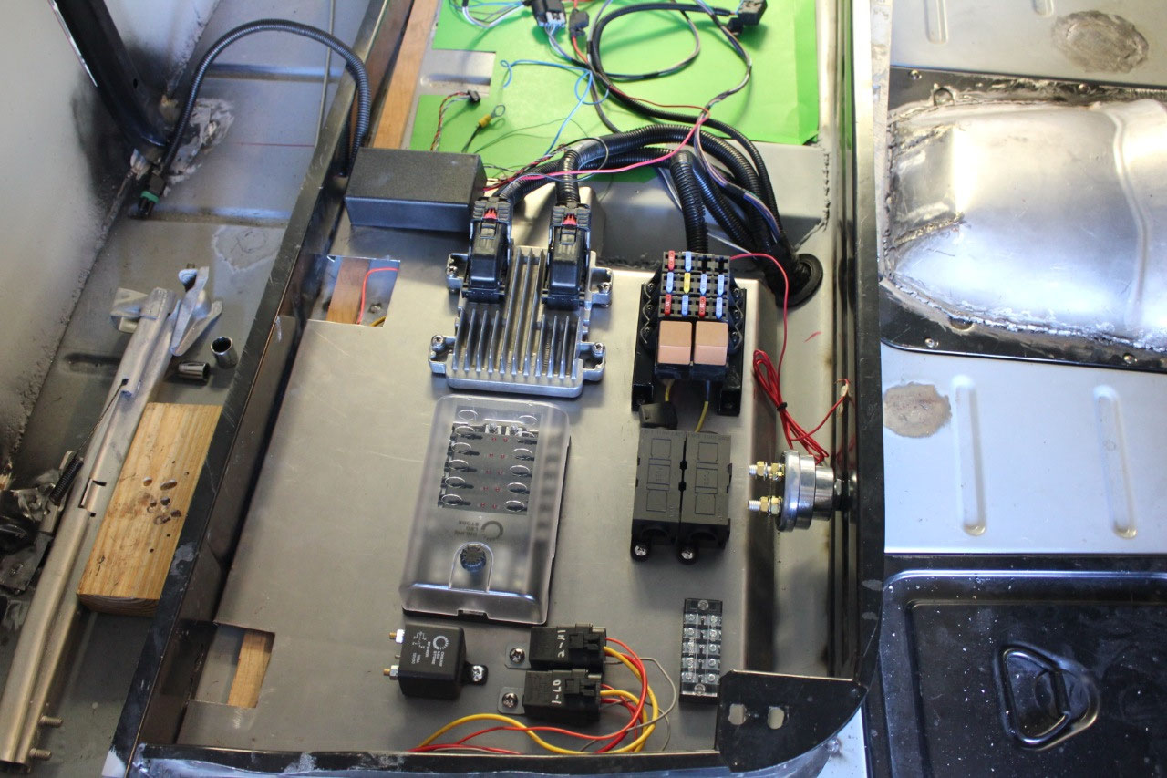
So I also mounted the GSS-2000 and an external Neutral
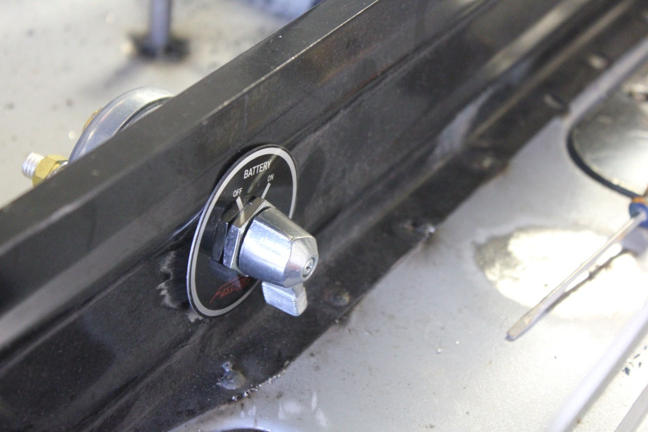
Safety Switch relay to the passenger’s side plate. I also decided that now would be a good time
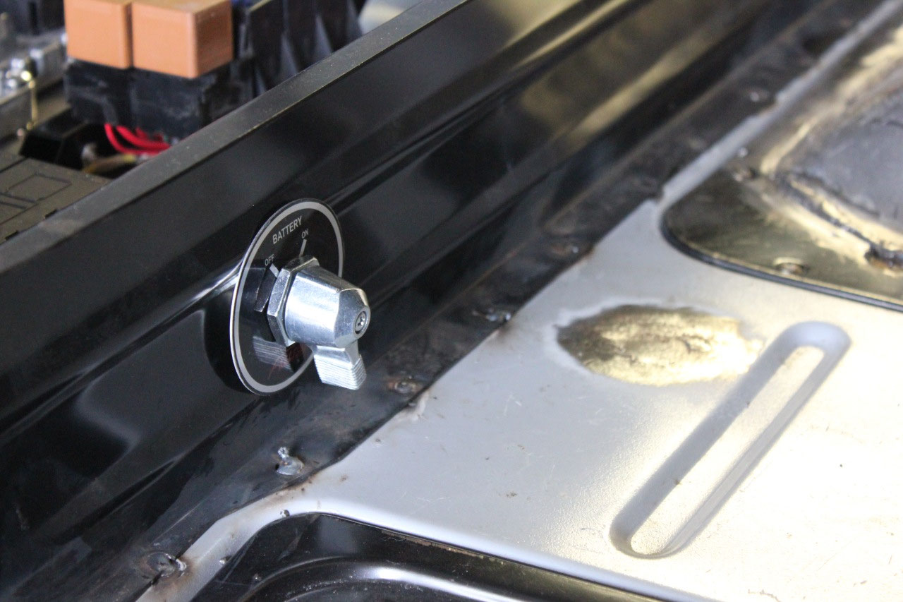
to add a Battery Master Shutoff Switch, so that I can easily remove power from
everything in case of an electrical problem.
I decided that I would prefer something with easy access, just in case,
so I wanted to mount it to the front of the seat platform on the passenger’s
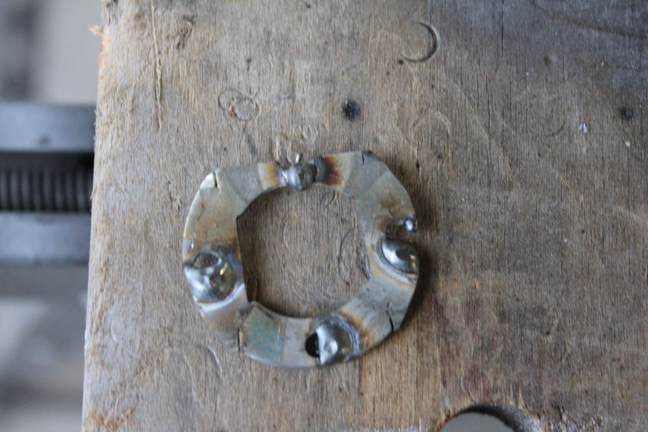
side. This is a 300A BIG switch, and
unfortunately requires a “double-d” hole to keep it from rotating when it is
switched on and off. Unfortunately, I
don’t know of any way of drilling a “double-d” hole, but I did manage to find
some sort of “double-d” washer from some alarm company on the internet that
just happened to have the right size “double-d” hole. So I bought a couple, at about $1 each, in
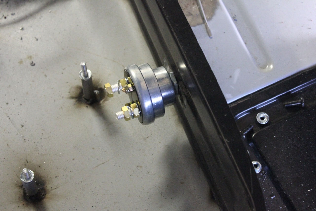
case I messed one up, drilled the correct round hole for the switch in the seat
riser and welded the washer to the opening to simulate a “double-d” hole. It worked perfectly!
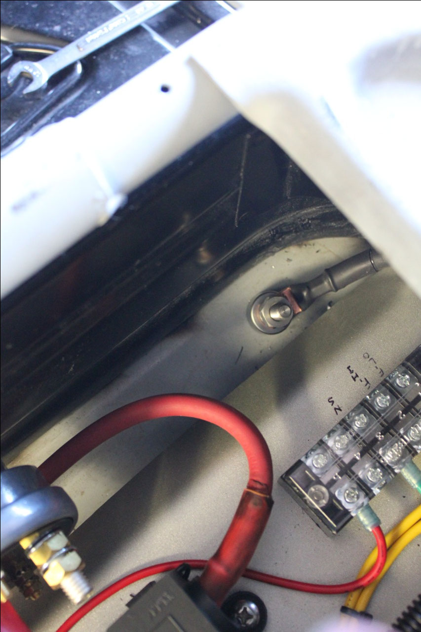
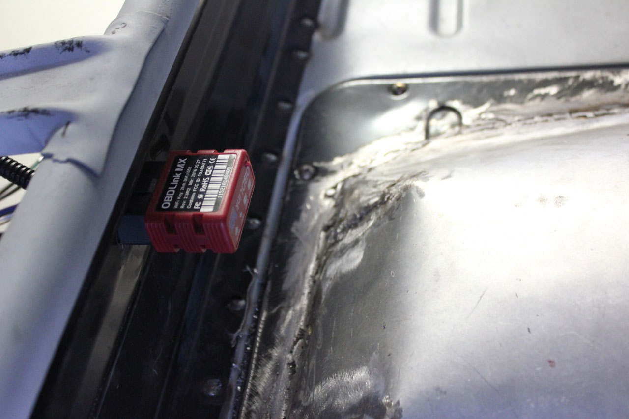
I also drilled and
shaped a hole in the center of the seat riser for the OBDII connector so I can
easily check for codes should I get one of those pesky “check engine” lights. I also added a large ground stud to the cab
near the battery switch. This will give
a master ground point for the electronics, and I will tie it directly back to
the battery.
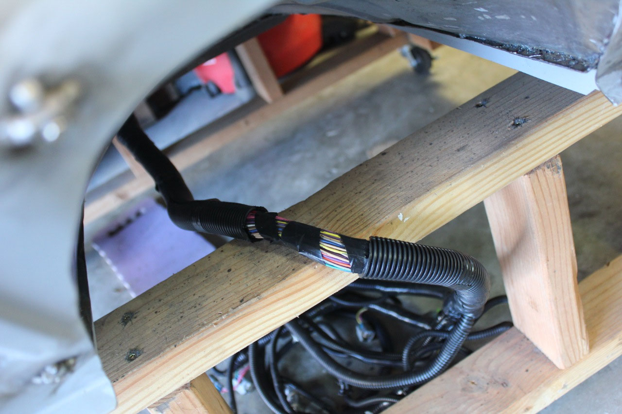
I took a closer look at the
engine harness, and found that while it would be difficult to lengthen, I could
easily add about 6 inches to the distance from the underseat grommet to the
engine by moving the breakout by the fuse panel and ECU about 6 inches further
back. This only meant I needed to cut the
sheathing between the grommet and the engine and add in a 6” piece of
sheathing. This should give me the
additional length I need.
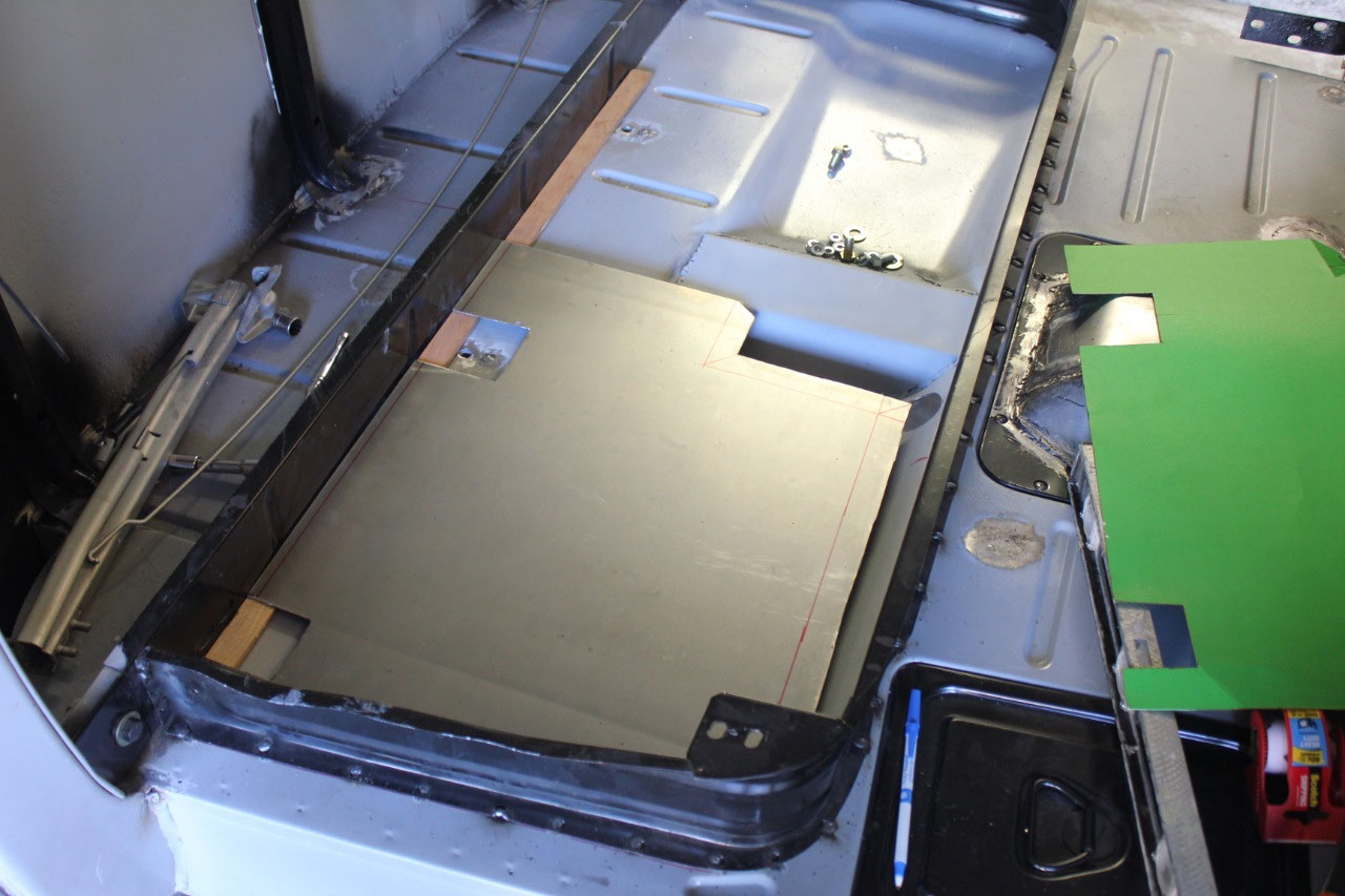
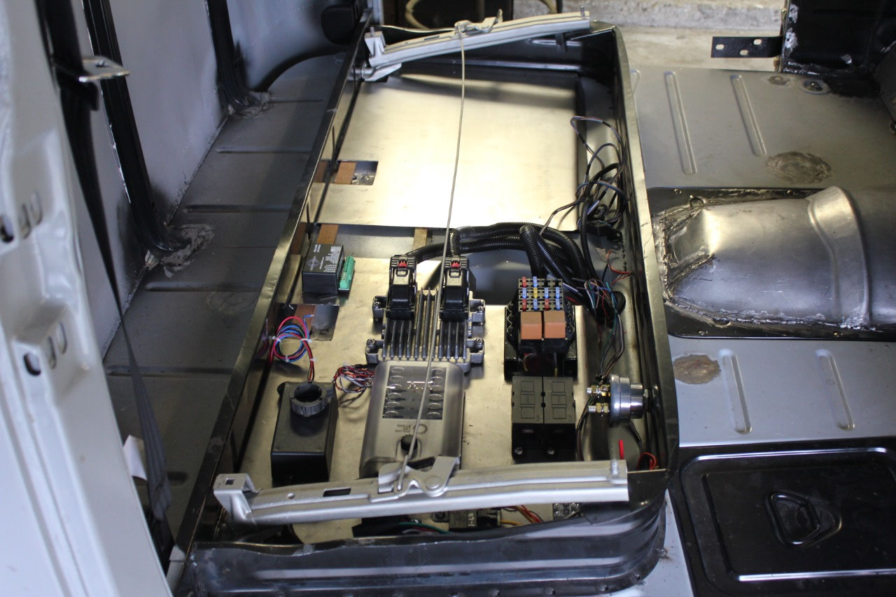
Now that the passenger’s side was done, I re-used the same
cardboard template, flipped it over and made a matching plate for the driver’s
side. I don’t have anything to mount on
it yet, but I will. The next step was to
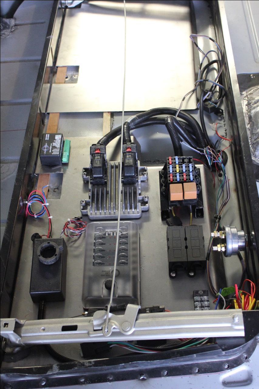
match drill the passenger’s side for all the components. I was originally just going to use just nuts
and bolts to hold all the components in place, but decided it might be
difficult to get at the bottom of the plate once everything was fully wired, if
I needed to replace something. So I got
out my trust Rivnut tool and pressed in Rivnuts at each location.
Now component replacement would be easy!
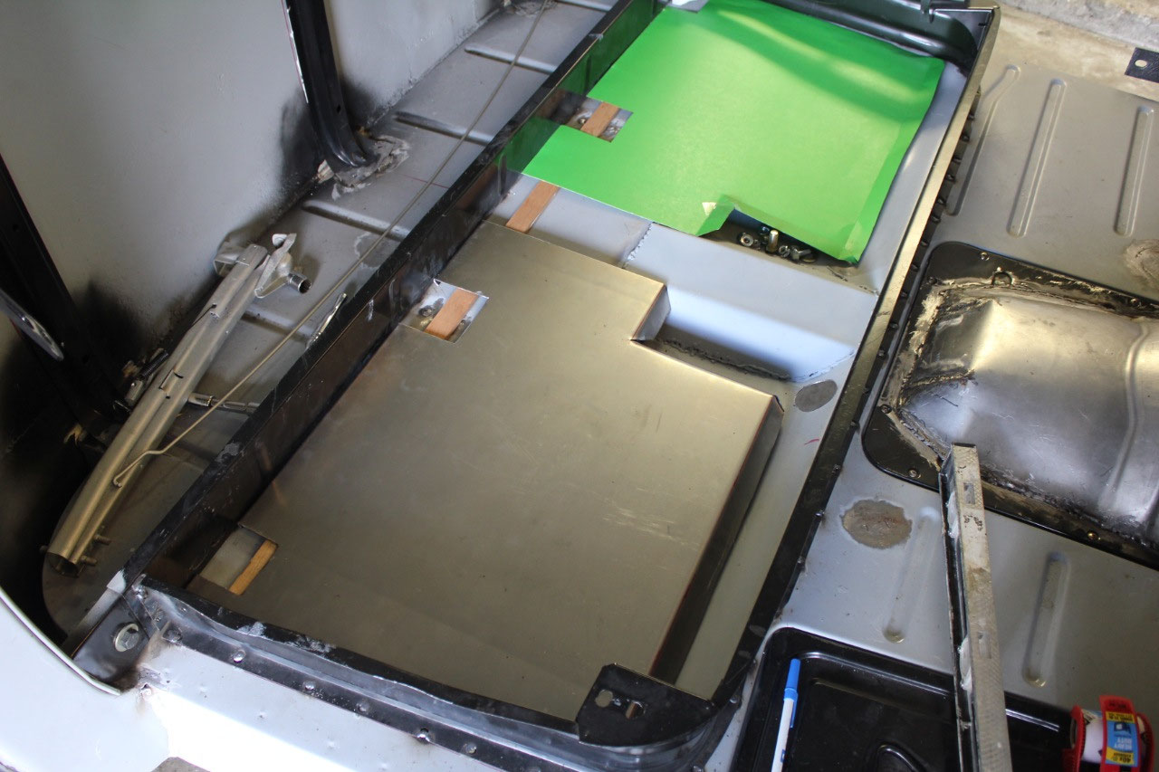
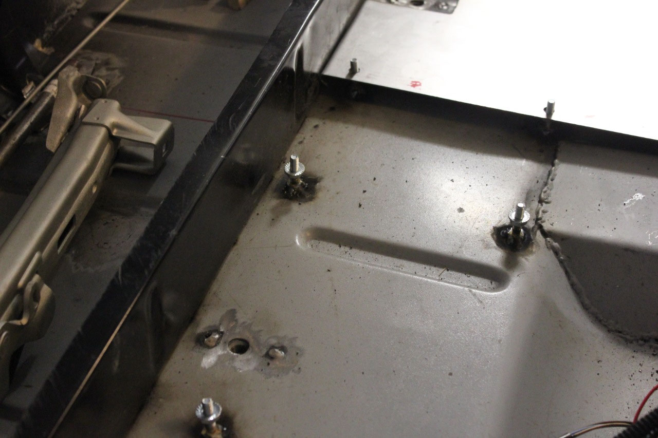
The last step was to figure out a way to mount the plates to
the floor. The floor is uneven in some
spots due to the storage are contours, so while I knew I would need some sort
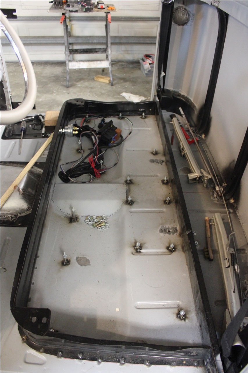
of standoff, they would be various lengths depending on location. In the end, I just used a bunch of ¼-20 bolts
of various lengths pointing up and with their heads welded to the floor. Using a level, I cut spaces for each of the
bolts and secured them with a nut threaded down onto the bolt. This gave a flat surface to drill and mount
each of the plates to the floor.
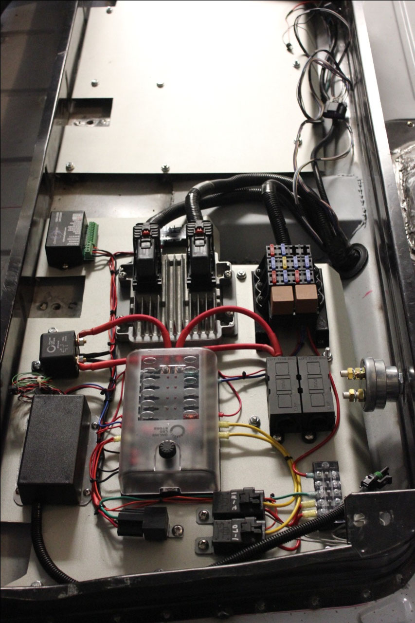
I drew up a schematic of the passenger’s floor plate circuit
and ran whatever wires I could while the plate was out of the truck. Fortunately, I already had a hydraulic
crimper, so I was able the various 4 gauge and 6 gauge wires connecting between
some of the larger components and it all came out looking pretty good. My neighbors were impressed!
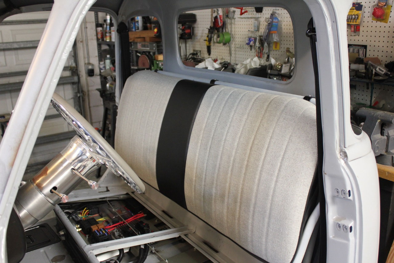
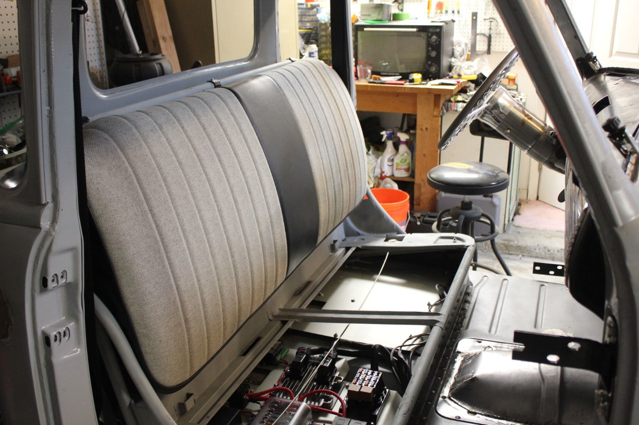
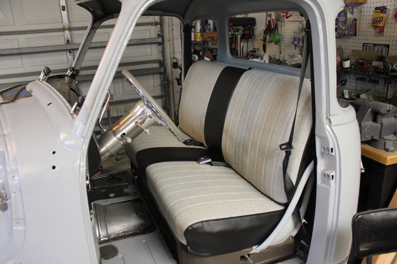
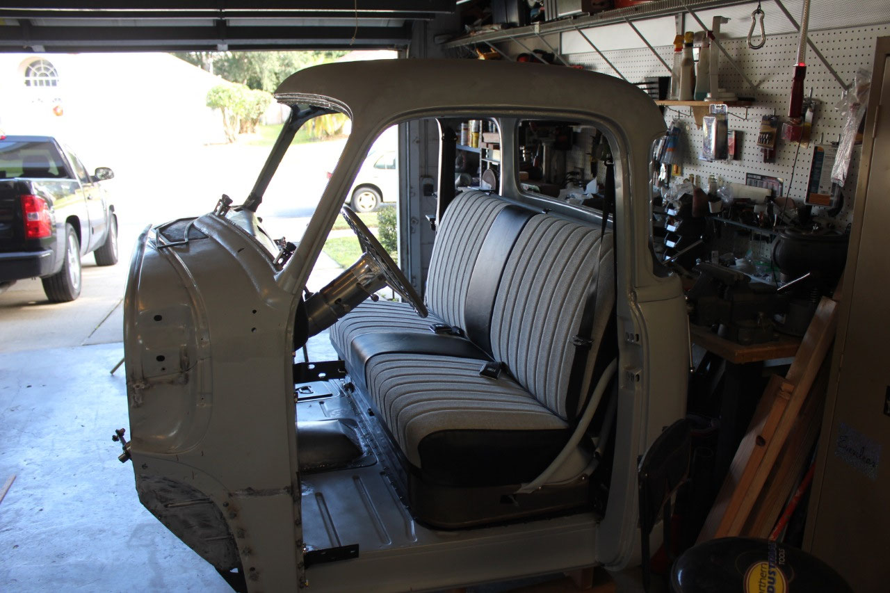
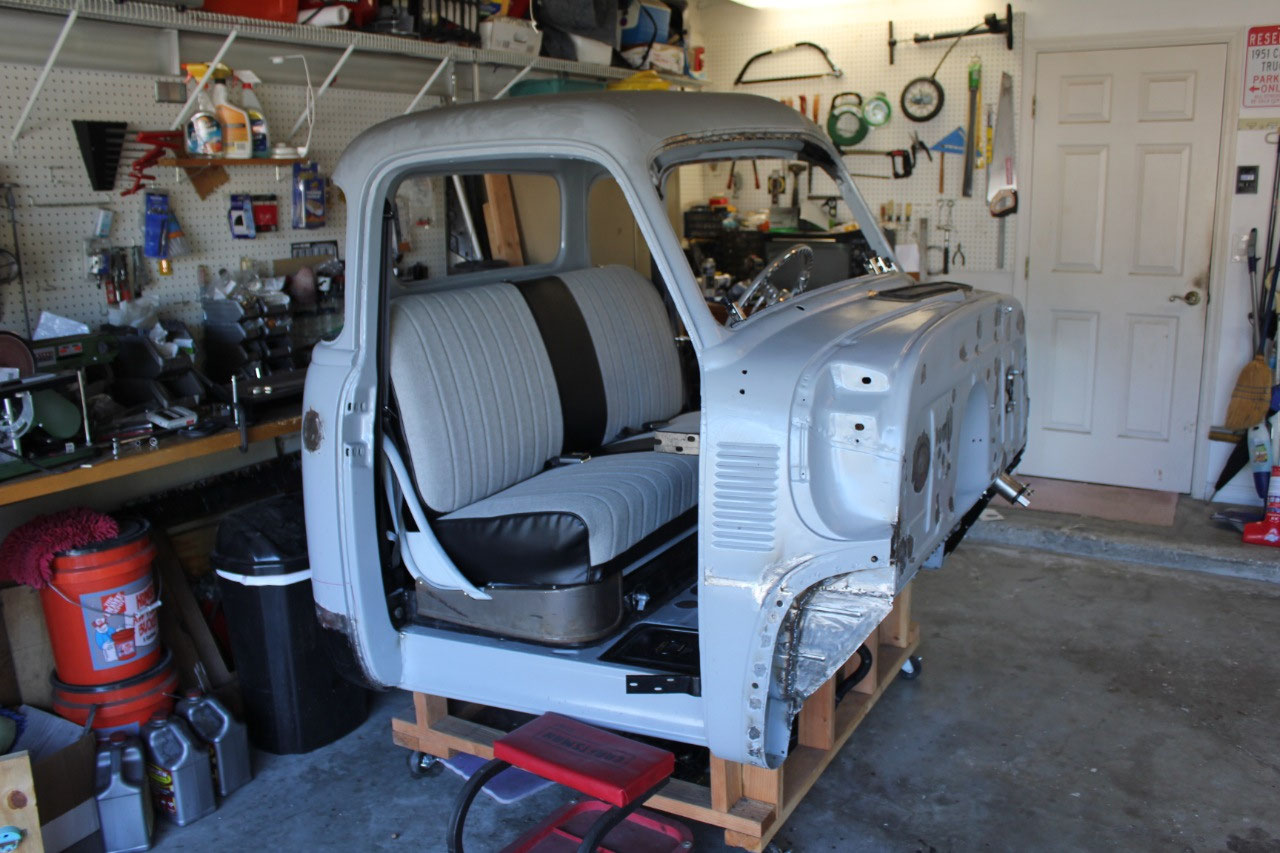
Now that the underseat wiring was mostly complete, it was
time to tackle the seat upholstery.
Eventually, I would like to have someone do a nice, professional custom
interior, but it’s expensive, and takes time.
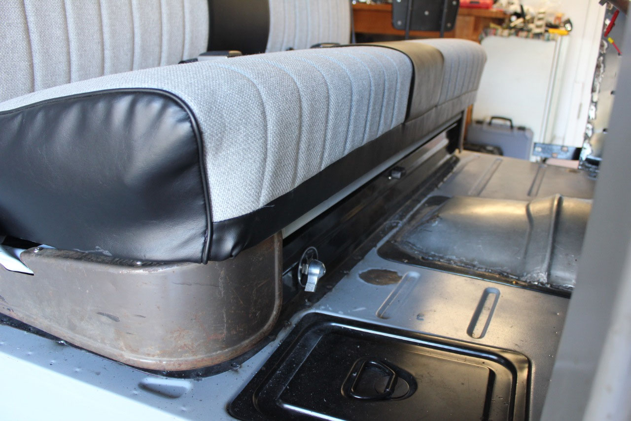
So for now, I found a nice cloth and vinyl seat cover with hog rings for
about $250. In addition, I installed all
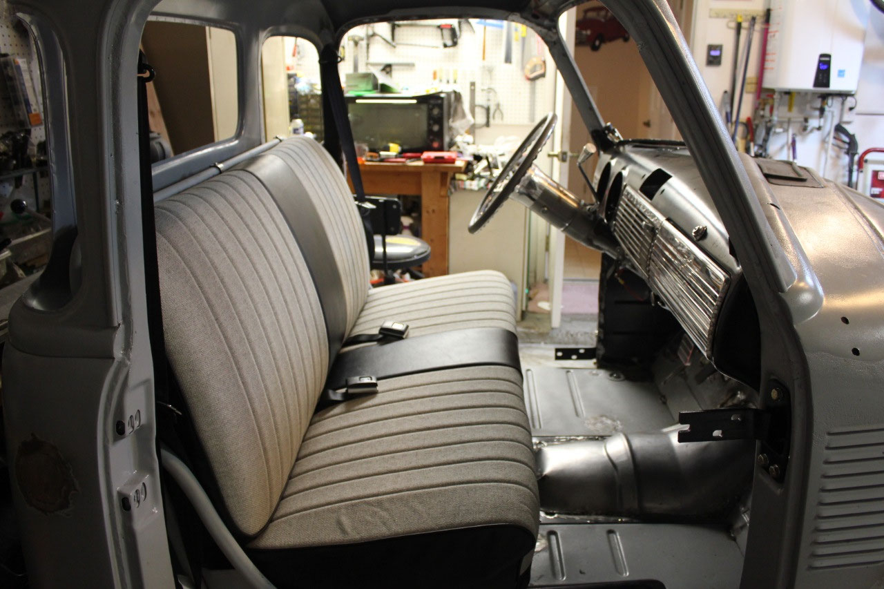
new foam and burlap for about another $100 doing all the work myself. It looks pretty good, certainly good enough
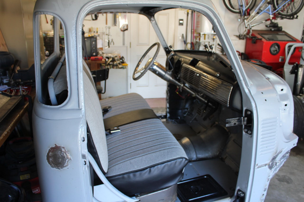
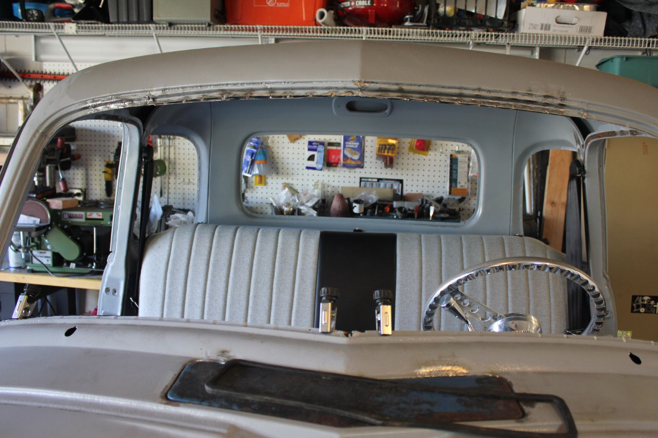
for now. I picked the black/gray
combination as just something neutral, where the seat riser and frame, steering
column, dash trim and carpeting will be black and the seat inserts, steering
wheel, headliner, and door panels will be gray.
This should look fine with the dark blue metallic I expect for the
exterior, but will go with almost any color should I change my mind.
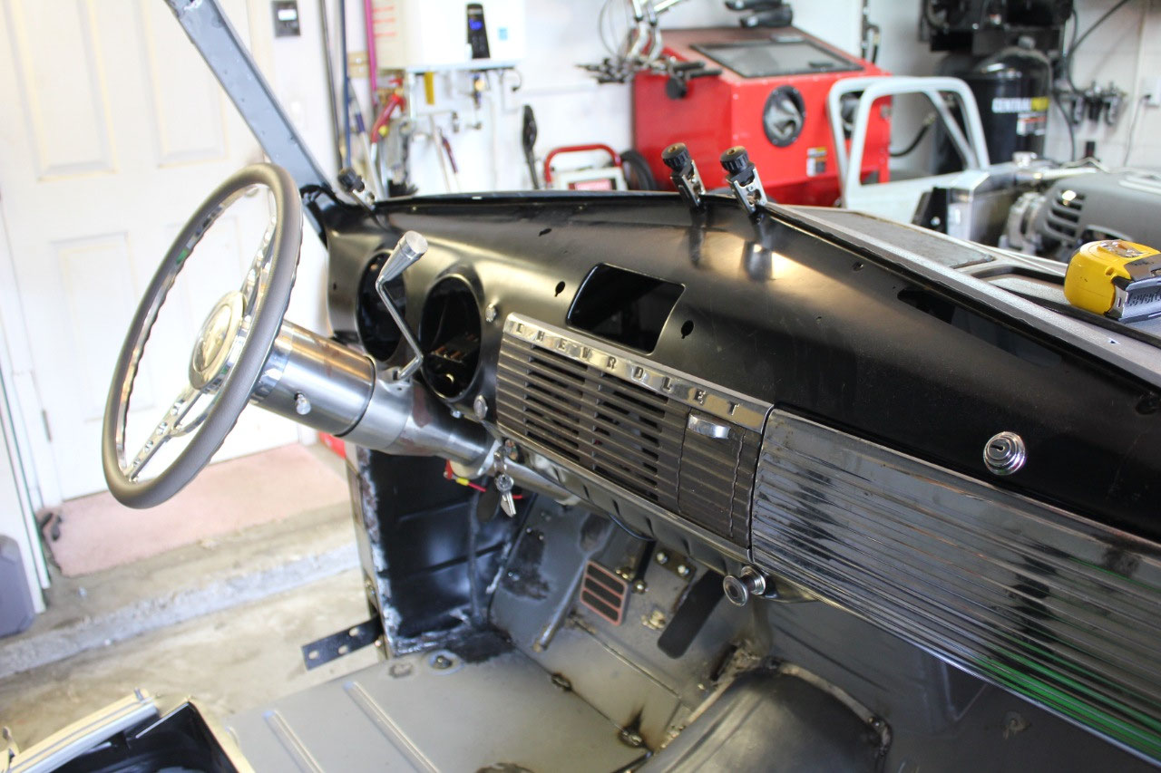
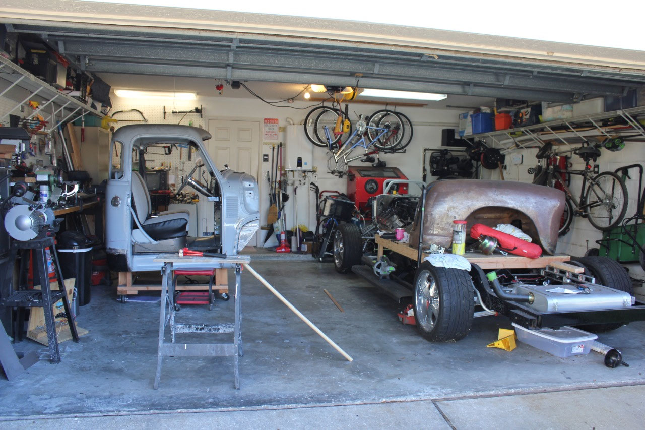
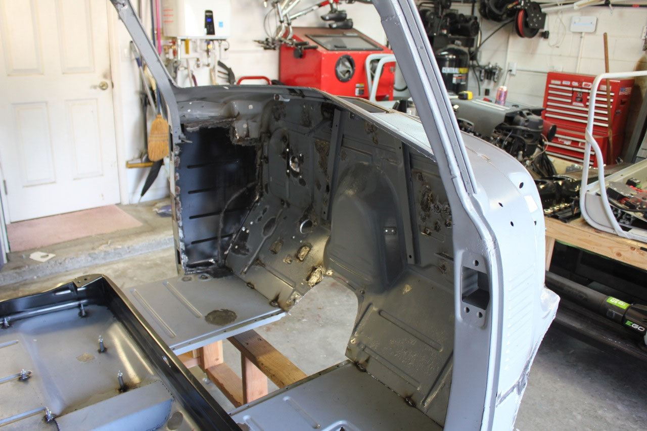
This completes all the cab work I had planned before
disassembly for bodywork and primer. The
dash is not yet welded in place, and I do have some metalwork to do around the
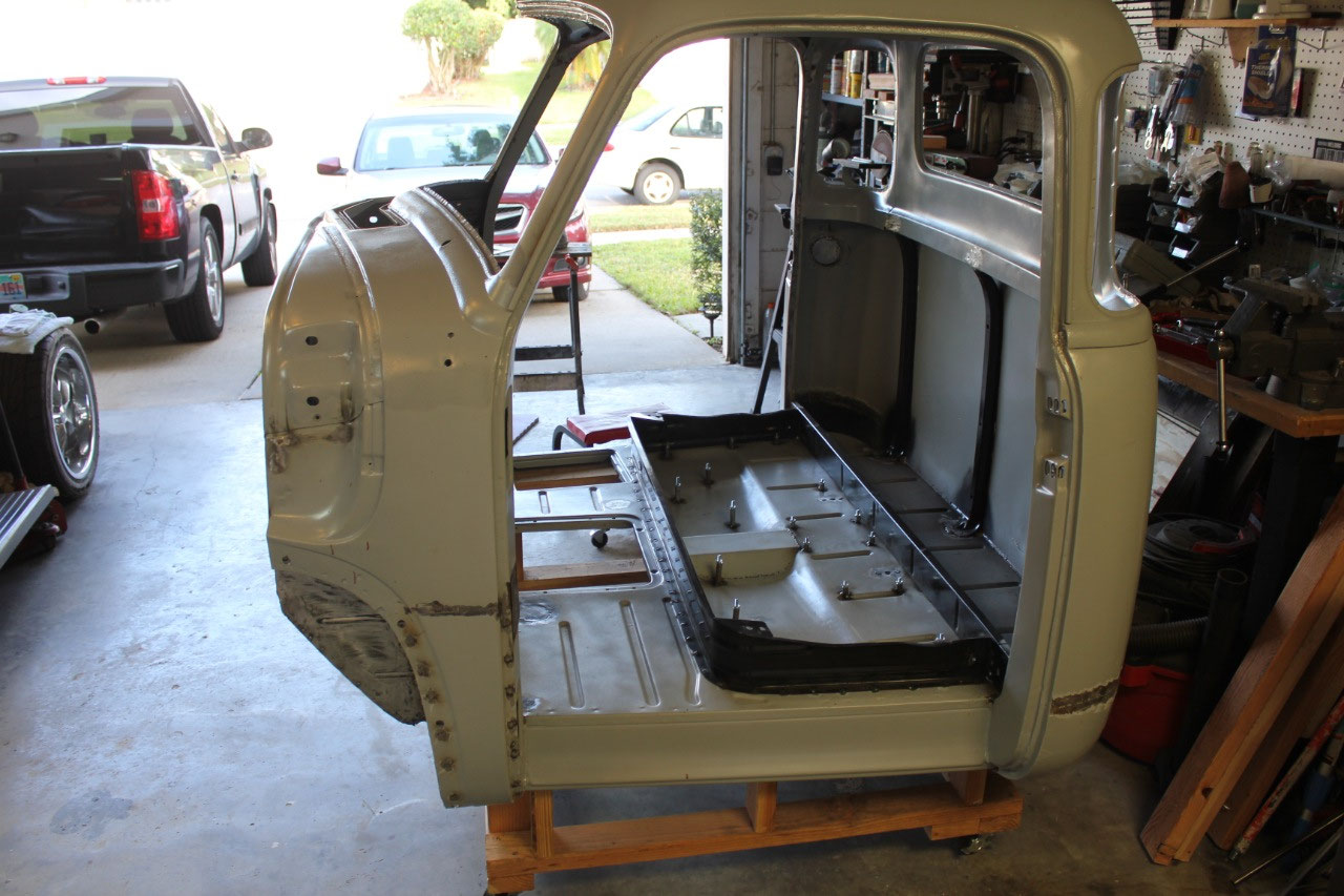
windshield after the dash installation is complete. Now is time to disassemble everything down to
the bare cab. It all looks so
naked! It’s really surprising how many
things need to be planned for as they may be more difficult after things are
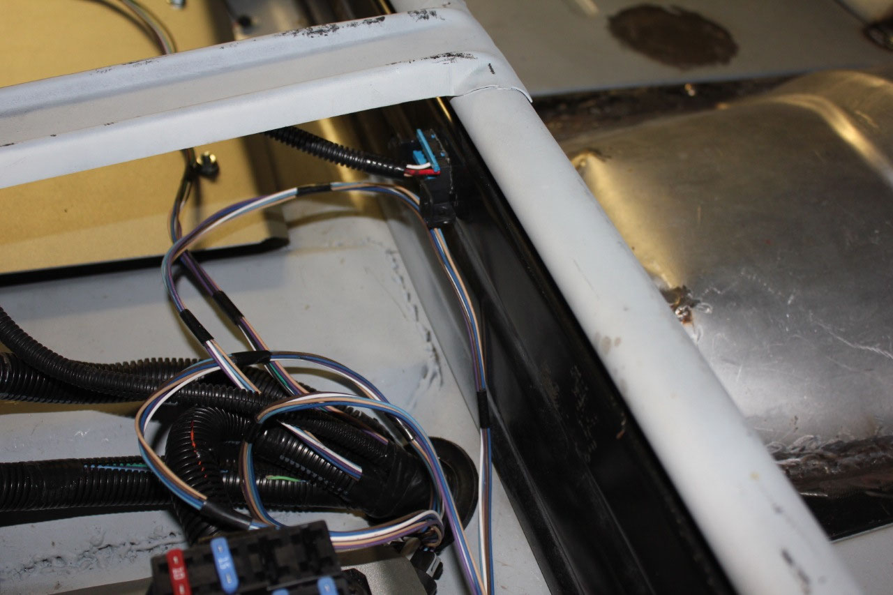
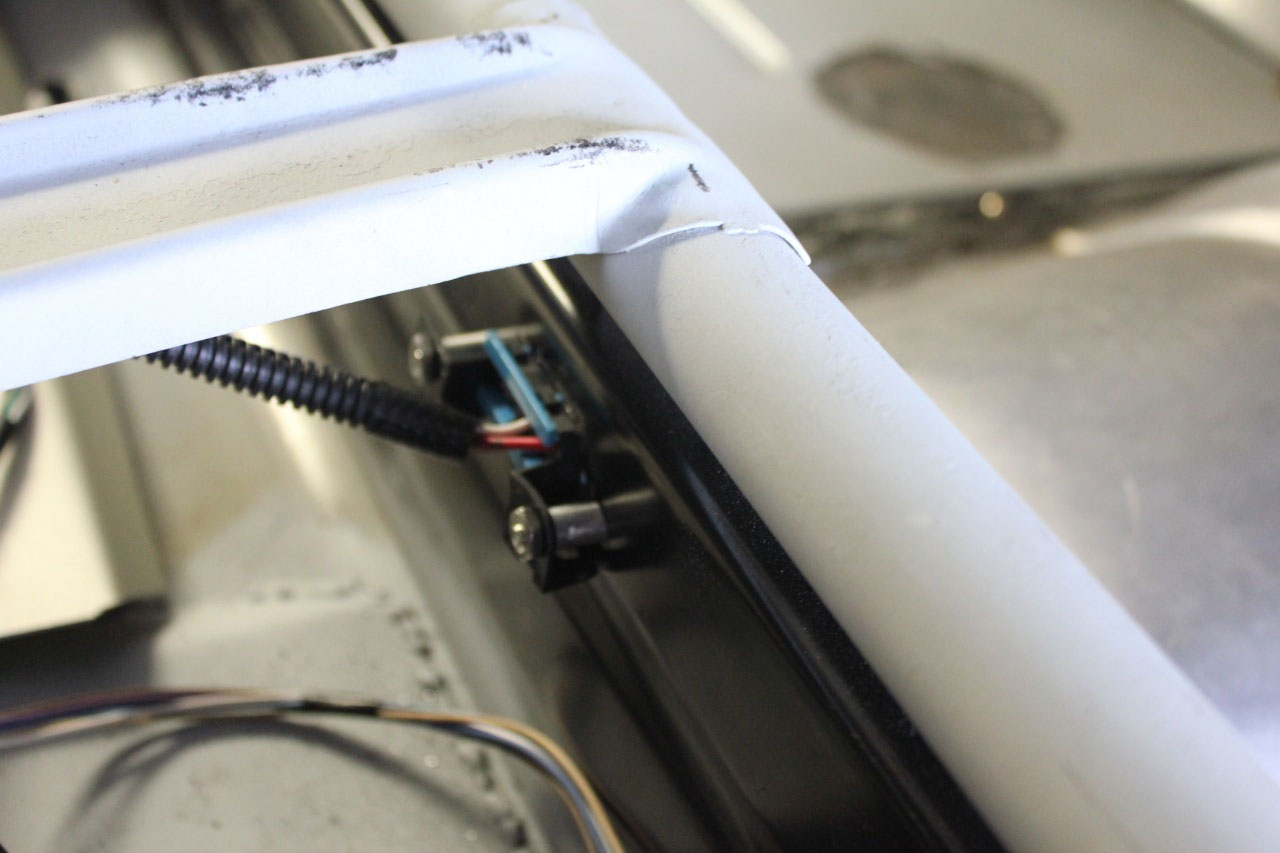
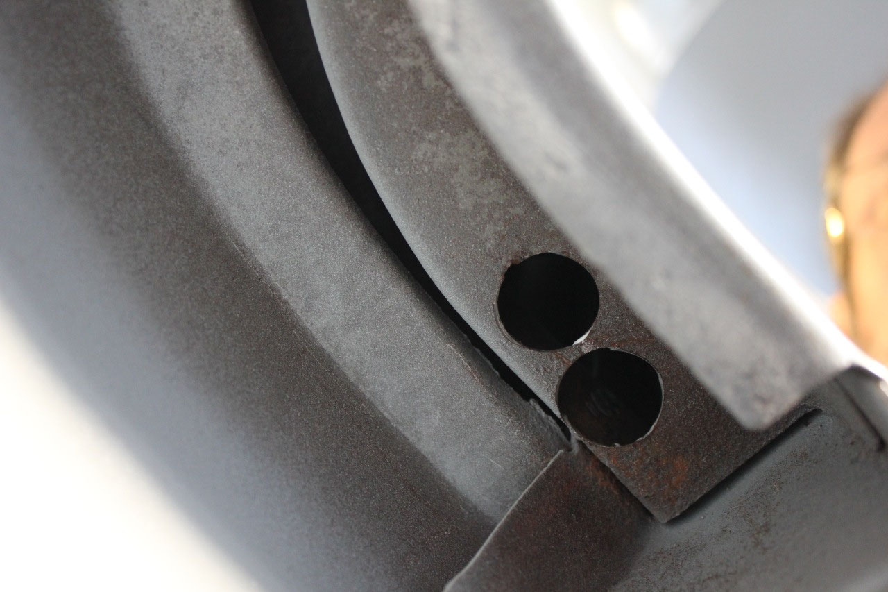
painted. At this point, I am expecting
to run wires between the dash and the underseat area through the A-pillars on
either side of the windshield. They are
hollow and fairly roomy, but when I tried to find a path down the B-pillar
behind the doors, I found it was blocked off.
Luckily I was able to drill a couple of holes in the b-pillar for wires
to pass.
The holidays are upon us, and it’s time to take a
break. The first task of the New Year is
to tackle the body and paint. I can
hardly wait!


2025-05-22