 Orlando, Florida, United States
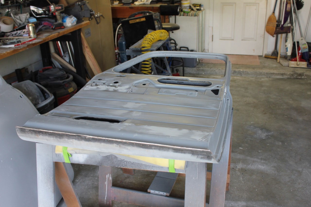
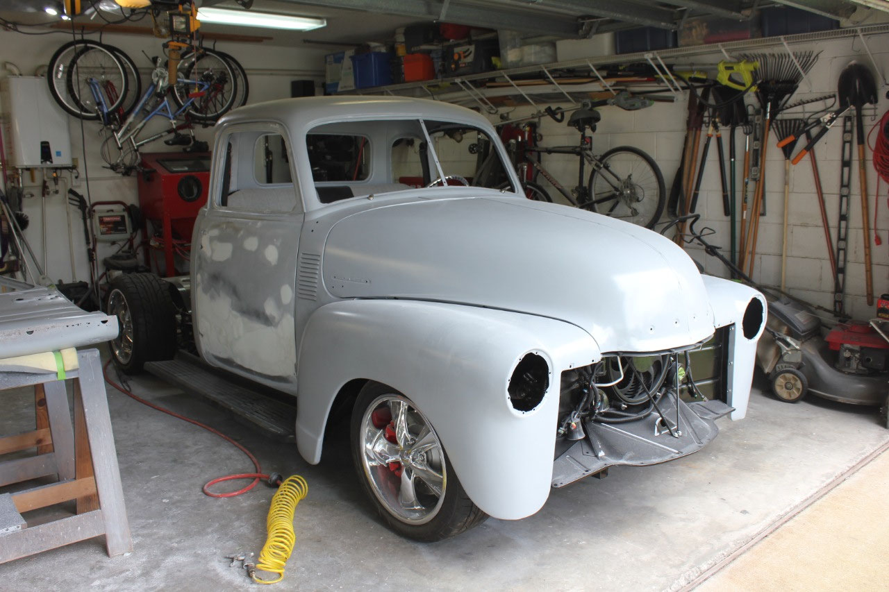
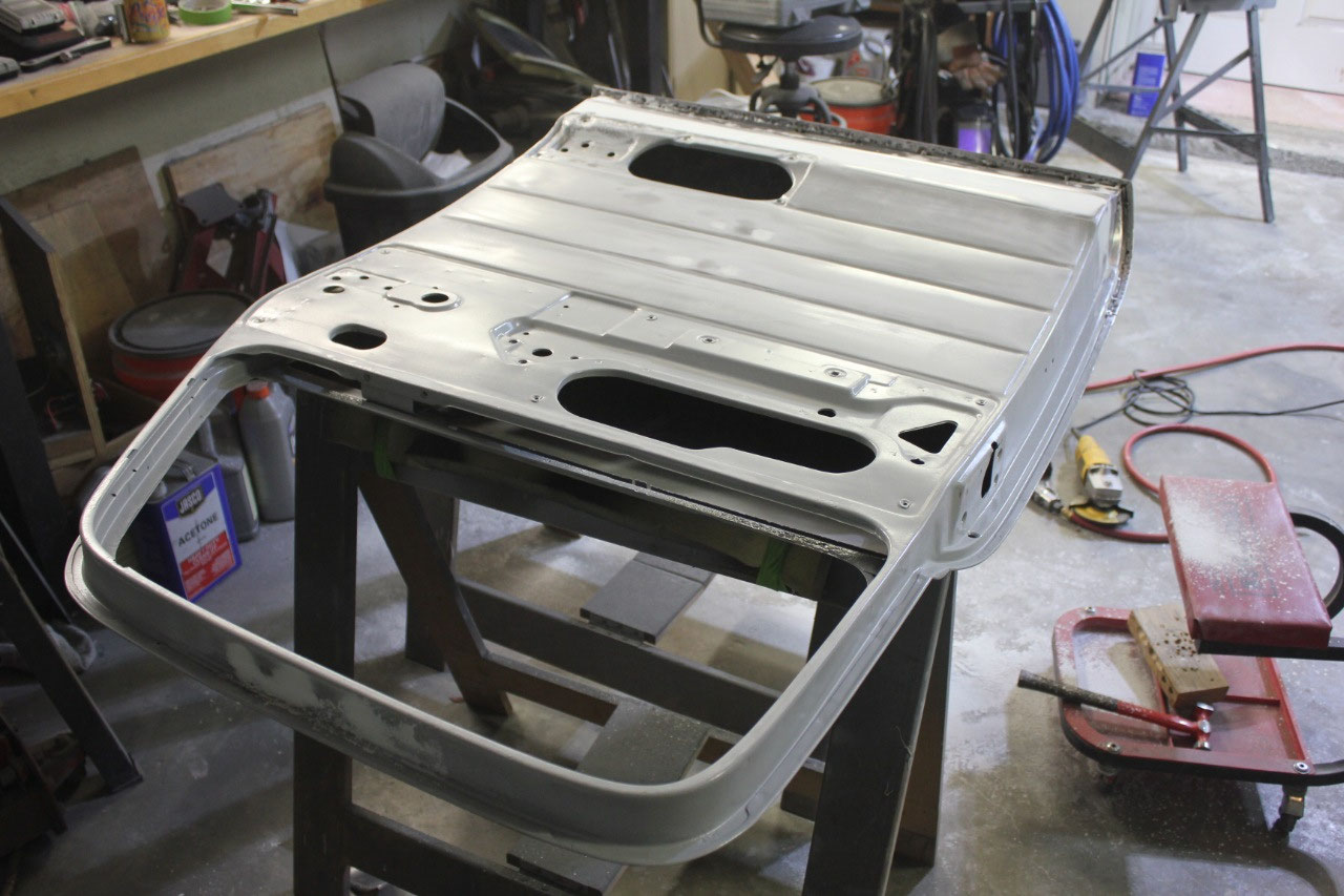
The time has come to attack the dilemma of the doors. 47-53 trucks have generally 2 different kinds
of doors. Early doors (47-50) have
turn-down exterior handles and one piece windows. Later doors (52-55.1) have push button door
handles and vent windows. Of course, my
ruck being a 51 is a hybrid between the two.
It has early door turn-down handles and late door vent windows. As such, replacement doors are not
available. Of course, replacement doors
are notoriously ill-fitting, so the first decision is to figure out what door
features do I really want. In addition,
there are 2 expensive purchases associated with rebuilding the doors – Power
window motors, and Altman latches. Both
of which are available for either early or late doors. The dilemma is that if I fail at rebuilding
the 51 doors that require early door Altman latches and late door Power Window
motors, any replacement door will be either an early or late door and one of
these parts will not be useable.
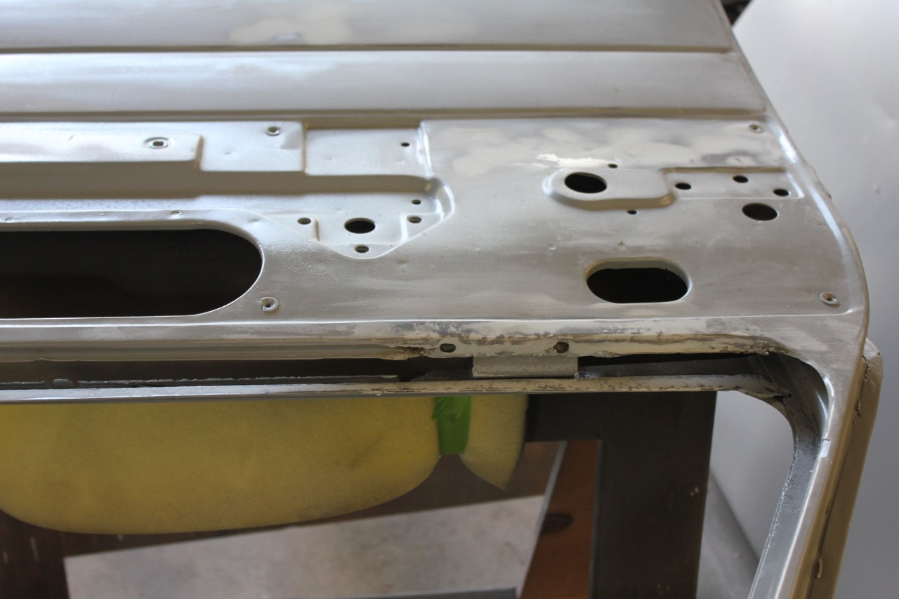
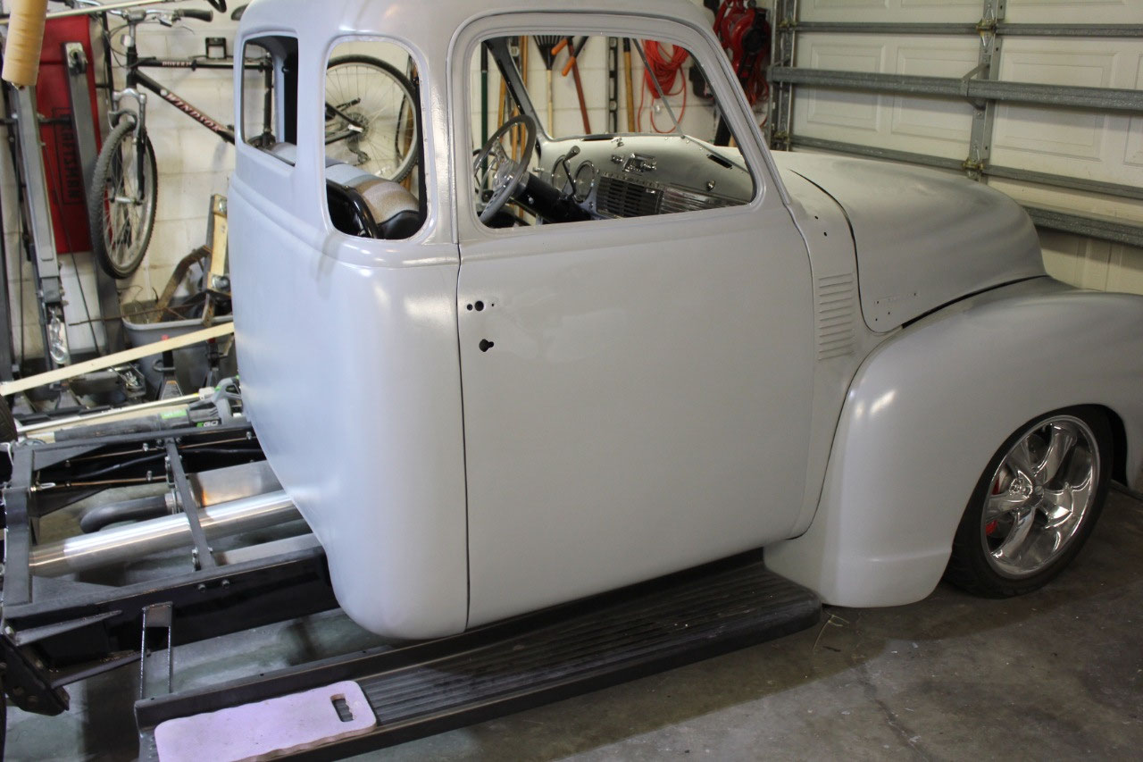
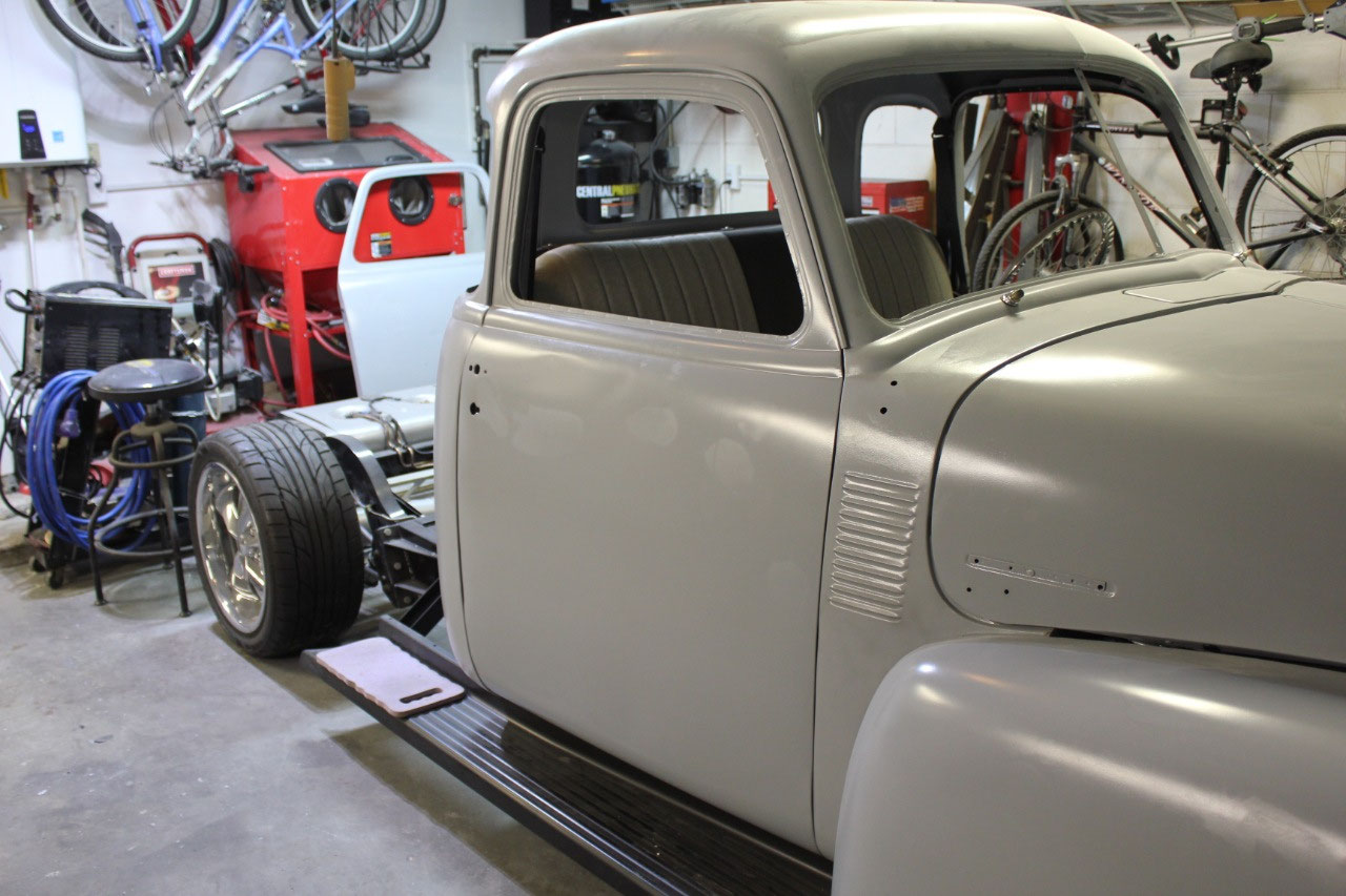
My existing 51 doors are in reasonable shape, they are
straight and fit reasonable well.
Both
have the typical rust at the bottom at both the inner and outer skin. The passenger door has been repaired and both
the lower inner and outer skins have been replaced. The previous owner has done a reasonably good
job, and it just needs a little bodywork.
There are a few small rust holes oddly enough on the inner skin behind
the door panel but these are easily repaired.
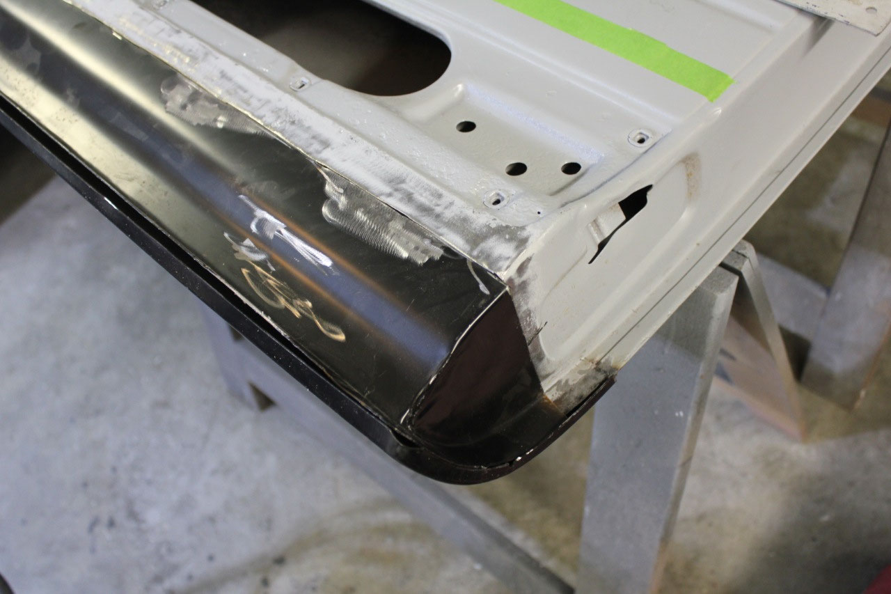
The driver’s door is actually in a little better shape overall, but the
lower inner and outer door skins need to be replaced. So at this point I decided to stick with the
51 doors. I actually prefer the
turn-down handles, and while everyone else seems to prefer one piece windows, I
like the look of vent windows.
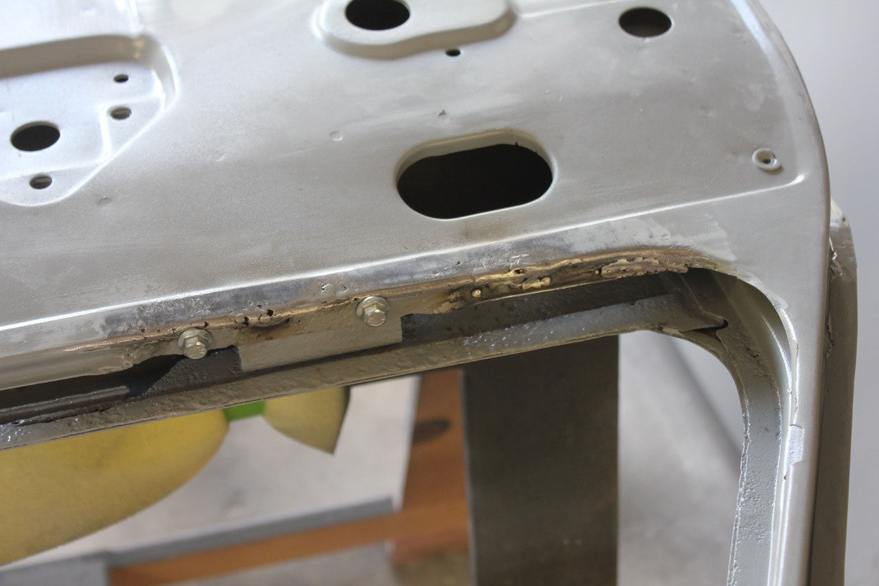
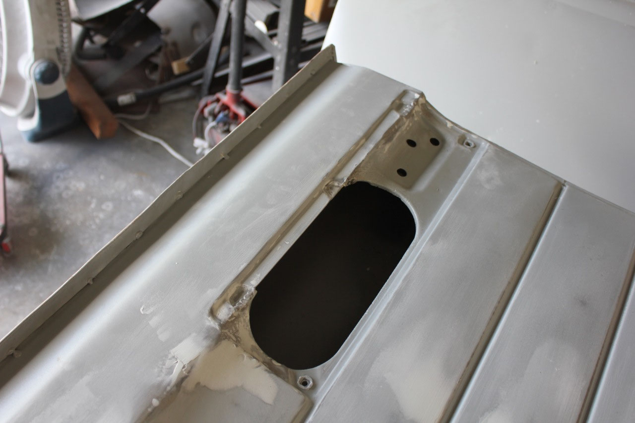
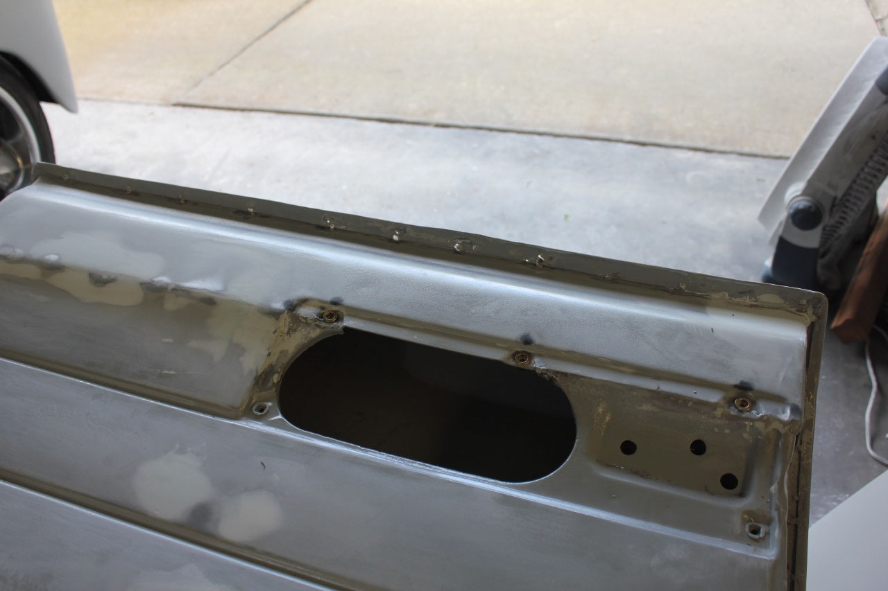
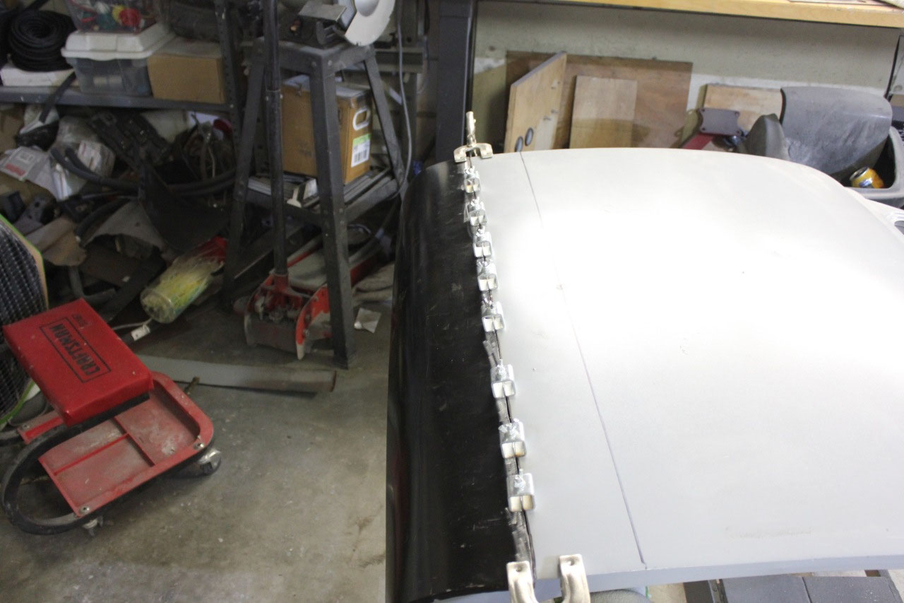
I started with the passenger door, welding up the small rust
holes on the inner skin and also welding up a few pinholes in the lower door
skin welds. I looked at how much of the
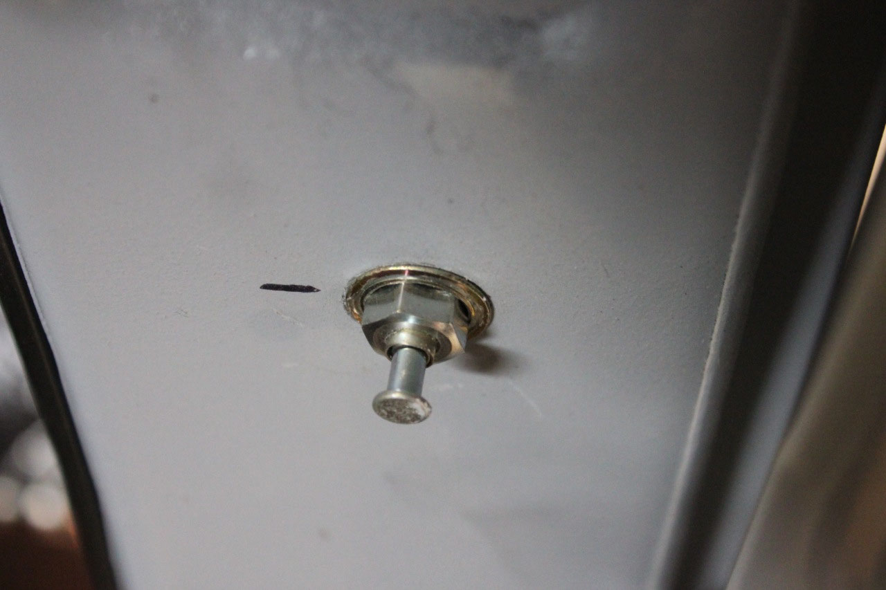
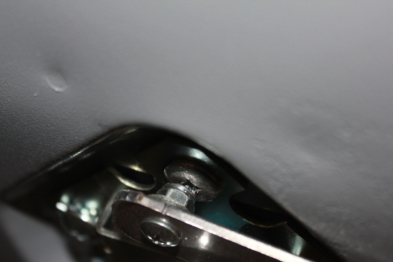
replacement skin had been used, and noticed that in the area of the lower hinge
access hole, they had removed all 3 of the access cover nuts, and there were no
nuts in place to attach the cover.
In
close inspection, the inner skin was slightly higher (maybe ¼”) at the hinge
cover location, so that if I installed rivnuts at the dimpled location, they
would not align correctly with the cover.
At this point, I welded up the holes in the cover, trimmed the lower
edge of the cover so that it would fit in the indentation and drilled new holes
where they would need to be. I then
installed rivnuts in the door and filed and welded the cover to fit. In the end, it all fits fine and the changes
to the cover are not noticeable.
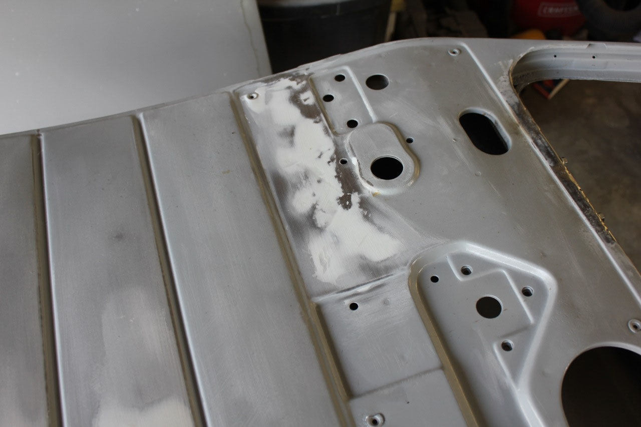
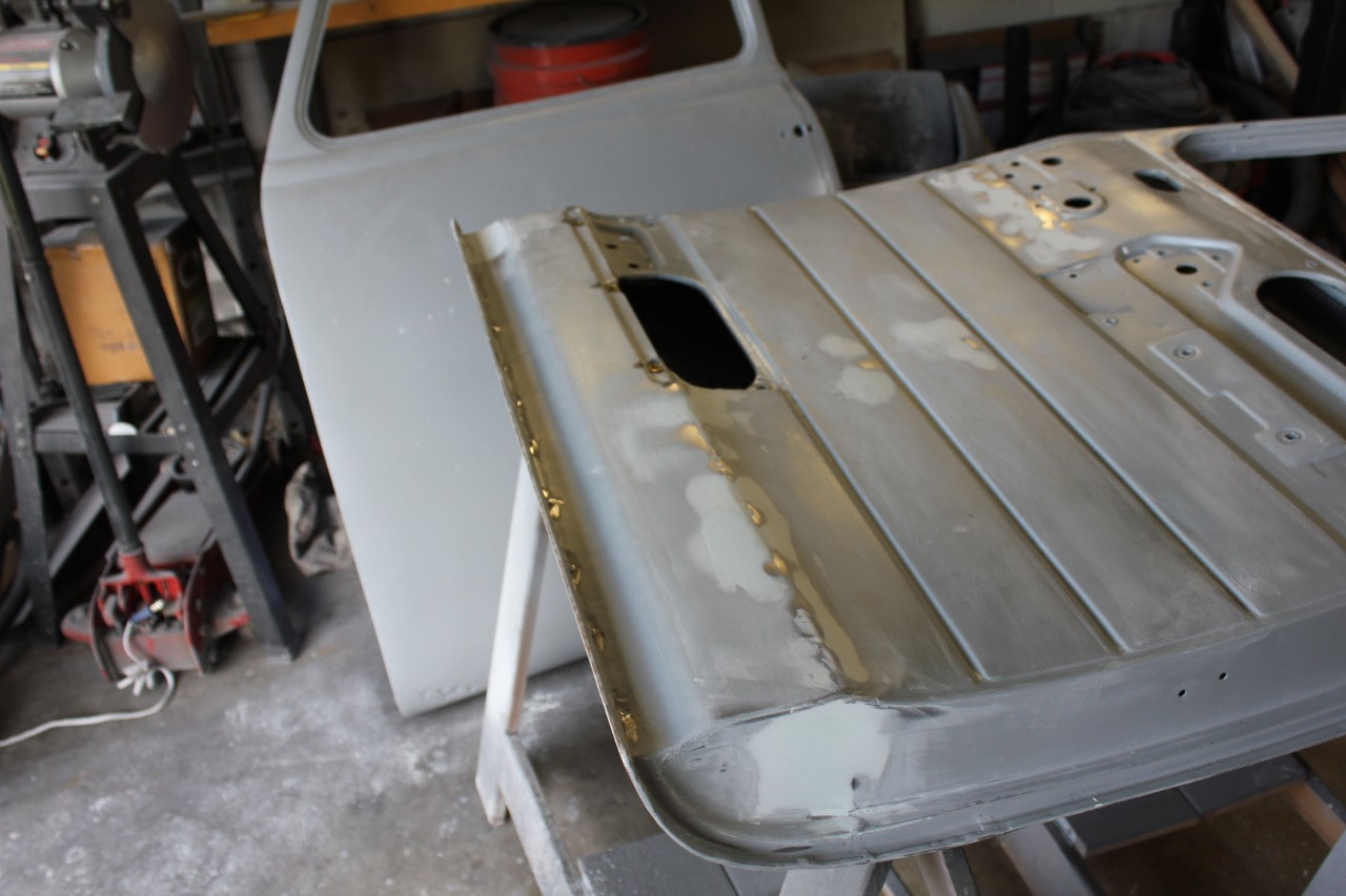
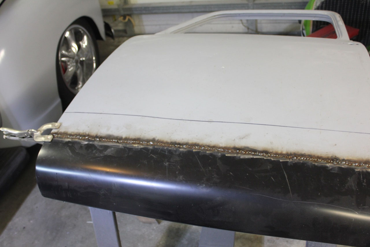
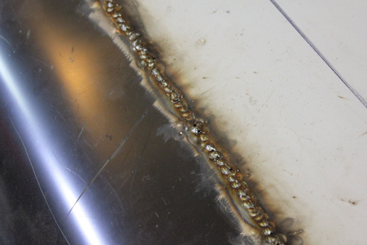
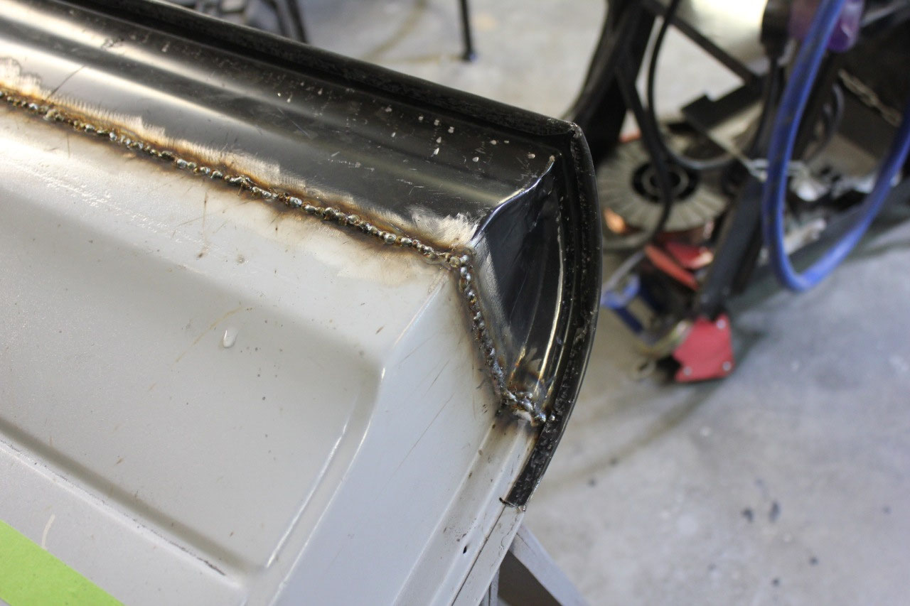
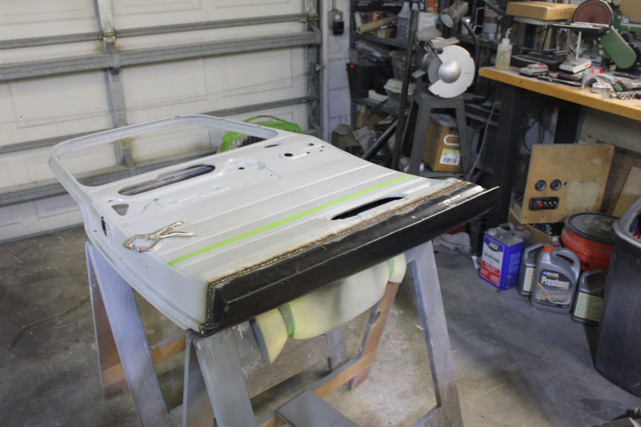
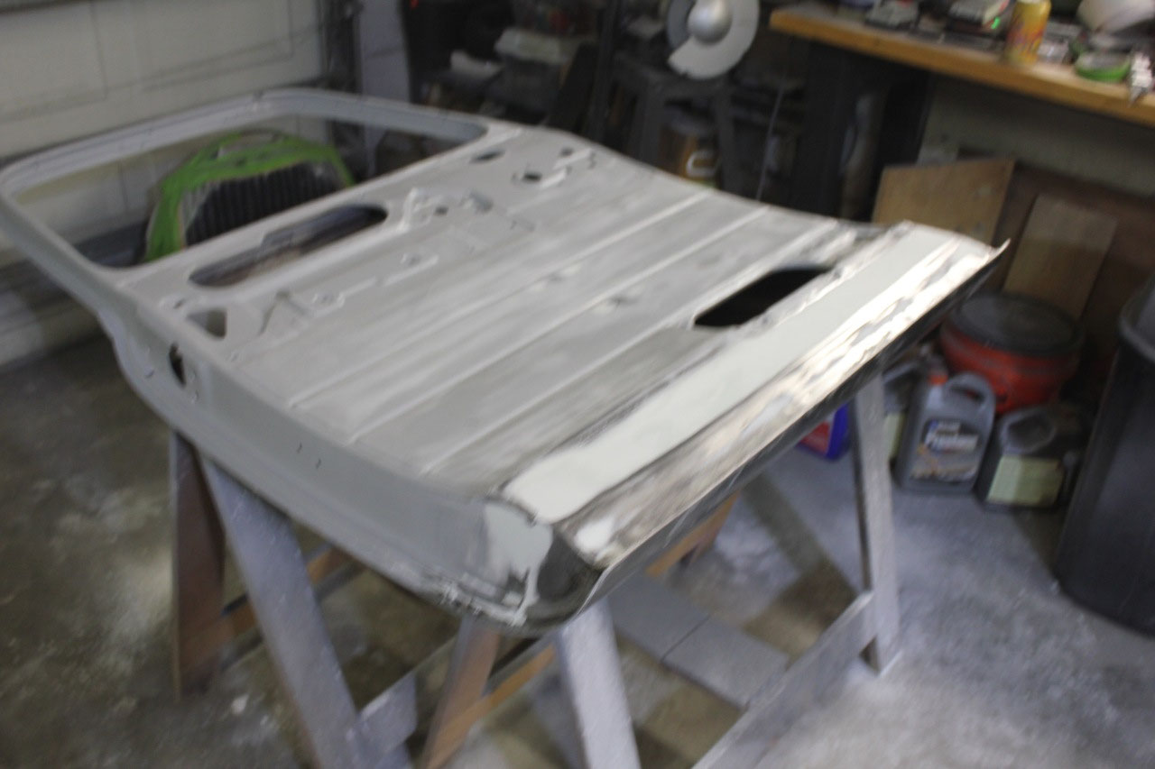
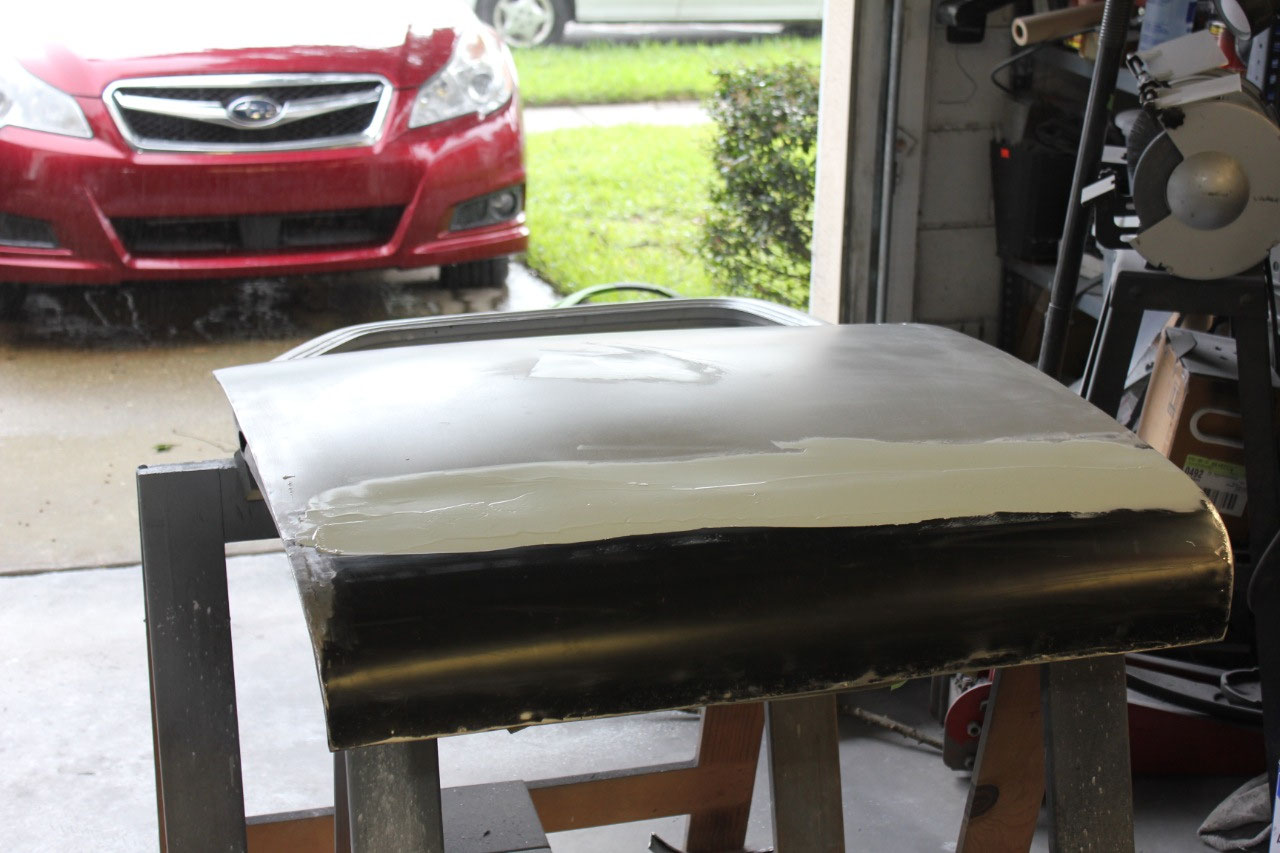
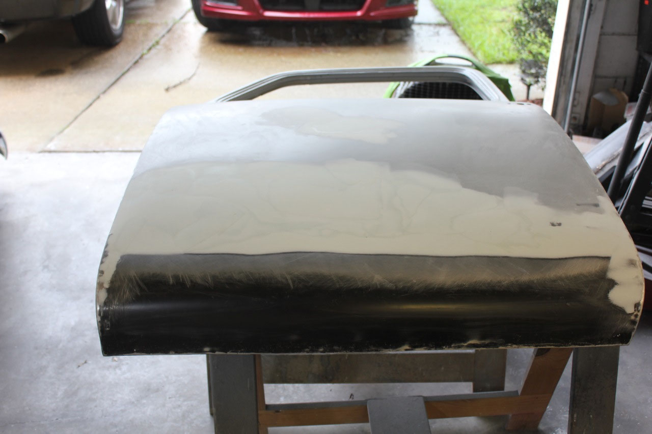
I cleaned up the welds at the door skin, a little hammer and
dolly work to make it all look straight and it looks pretty good. Filled in the imperfections with body filler
and all looks great! A little trial fit
on the cab and all looks good. Re-primed
the door both inside and out and it all fit fine. Now I’m ready to tackle the driver’s door.
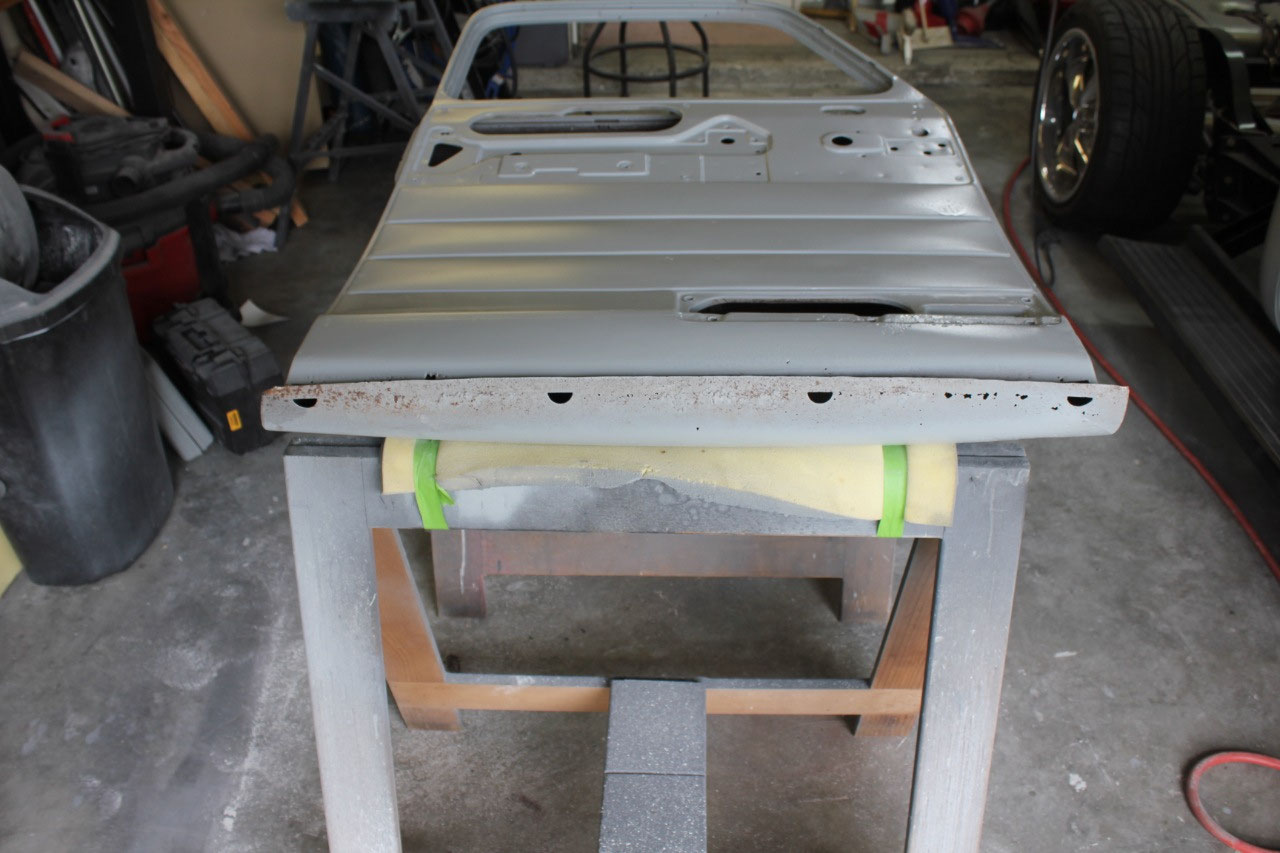
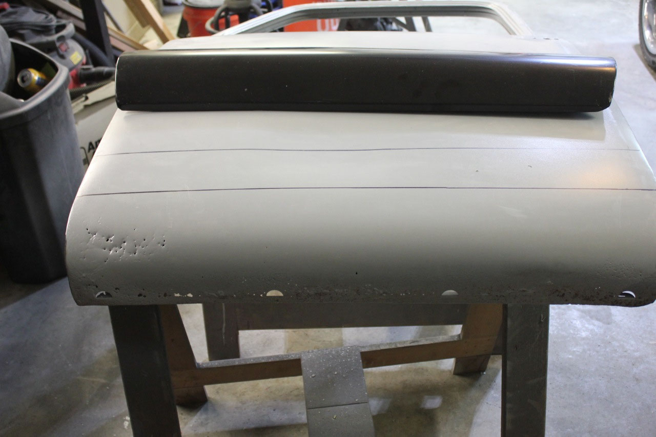
The hardest part of replacing the lower door skin is getting
the lower door edge to remain in the same point in 3-dimensional space.
I watched a lot of YouTube videos and there
are arguments about whether to replace the inner or outer panel first, but in
my case, the inner panel had already had the lowest inch or so removed, and the
outer skin was not exactly where it needed to be. But I decided that since the edges of the
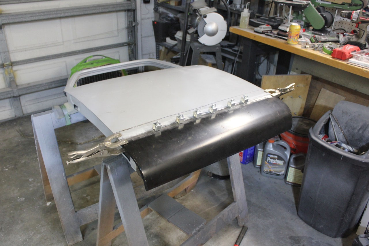
inner skin was mostly in place, I would replace the outer skin first. I trimmed up the outer skin replacement panel
as short as I could to cut out all the rust, but to allow for a second
replacement if I screwed up. Now I was
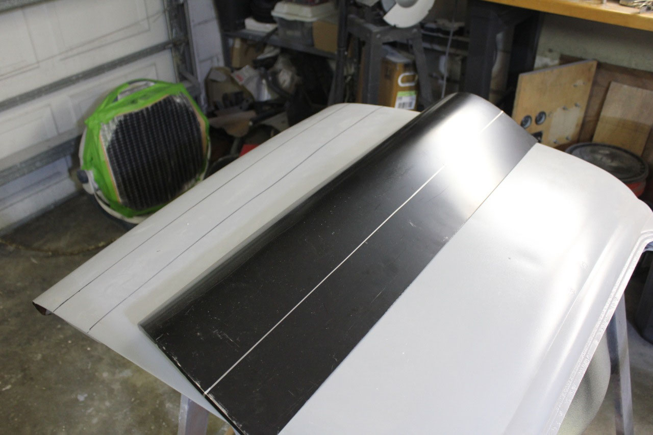
able to set the outer skin in place and weld it up. Next I cut out the old inner panel and trimmed
up the new inner door panel leaving the lower nuts of the lower hinge opening
in place so the hinge cover would fit without modification. Once the inner panel fit well, and I went
ahead and welded it in place also. Then
I used the door skin body hammer to fold over the outer skin edge and it looked
pretty good.
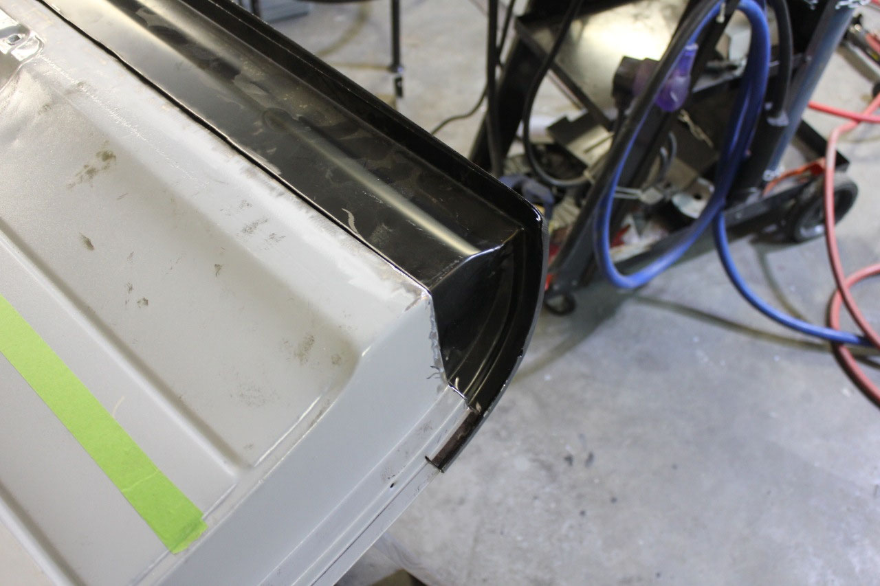
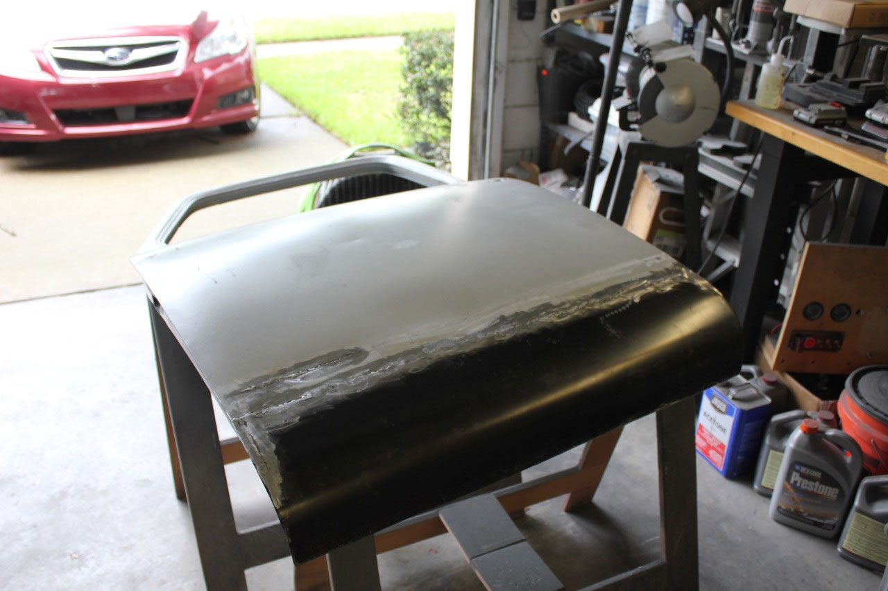
Unfortunately, it just didn’t fit! While the overall length of the door was
correct, the lower skin fold over at the bottom was too long and would hit on
the bottom of the cab rocker panel before the door was fully closed.
I was not off by much, somewhere between 1/8”
and ¼”, but enough that it needed to be reworked. Fortunately, I had not been pleased with the
outer skin fit on the replacement panel, so I had ordered one from a different
manufacturer. It turns out the second
manufacturer had remarked one from the original manufacturer so the fit was the
same. It just meant that I had a second
exterior panel.
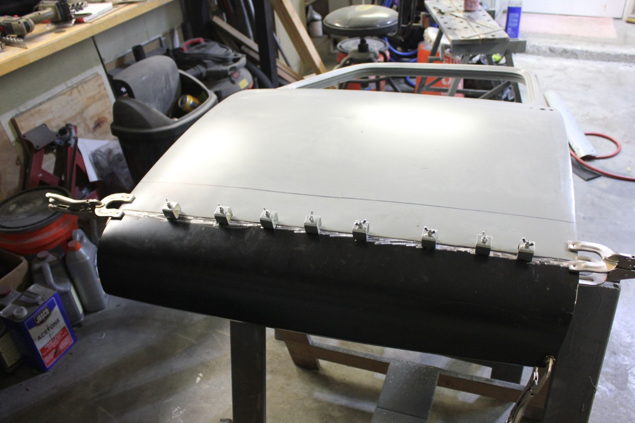
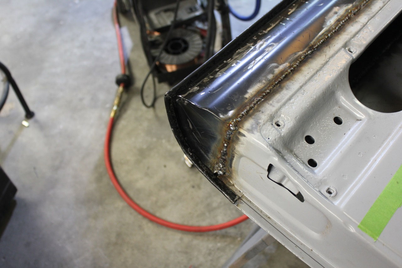
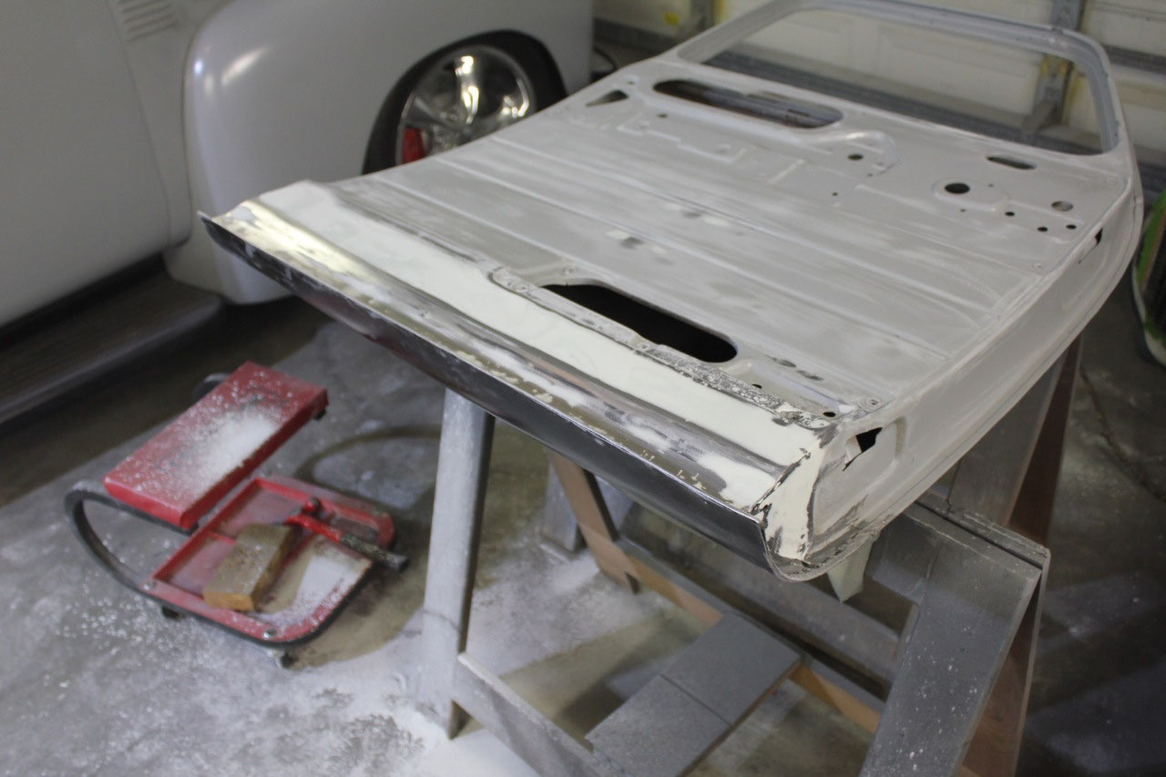
When I installed the first exterior skin, I had trimmed the
skin to just above the rusted areas so that I could replace it again by cutting
above the weld which is what I did. I
also did some trimming on the inner panel to address the fold over length. I welded in the new panel and paid special
attention as I folded it over to keep the length as short as I could, and this
time it fit perfectly. The door would
bottom out at the latch area before the bottom would contact with the rocker
panel. Then it was just a matter of
finishing up the bodywork and re-priming before installation.
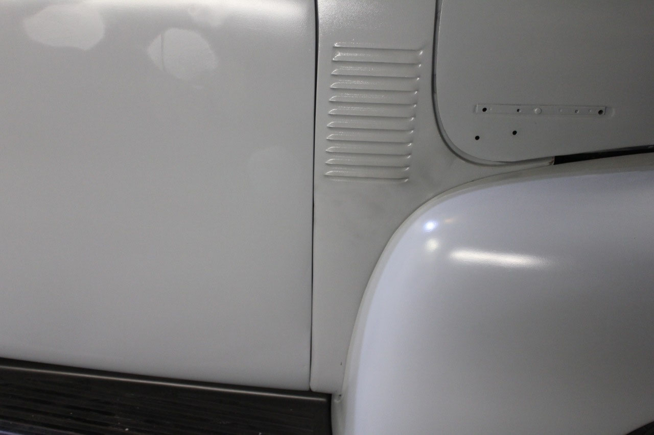
Everything fits pretty well, the door gaps are not great,
but nothing rubs. The next step is to
install the latches. Now the original
design of door latches on these trucks is terrible at best. They don’t work, and are notorious for
releasing when you go around the corner and the cab flexes at all. I know this because when I bought the truck,
the doors and latches were installed, but I zip-tied the doors closed while I
trailered it home. Sure enough whenever
I stopped, at least one of the doors had become unlatched and here held closed
by the zip-ties. The original latches
are terrible, but the Chinese replacements are supposed to be even worse.
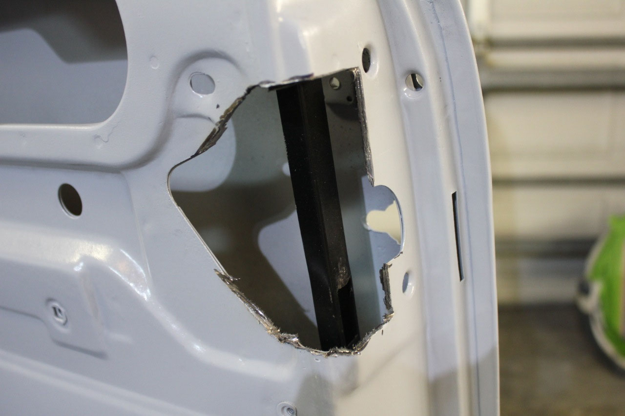
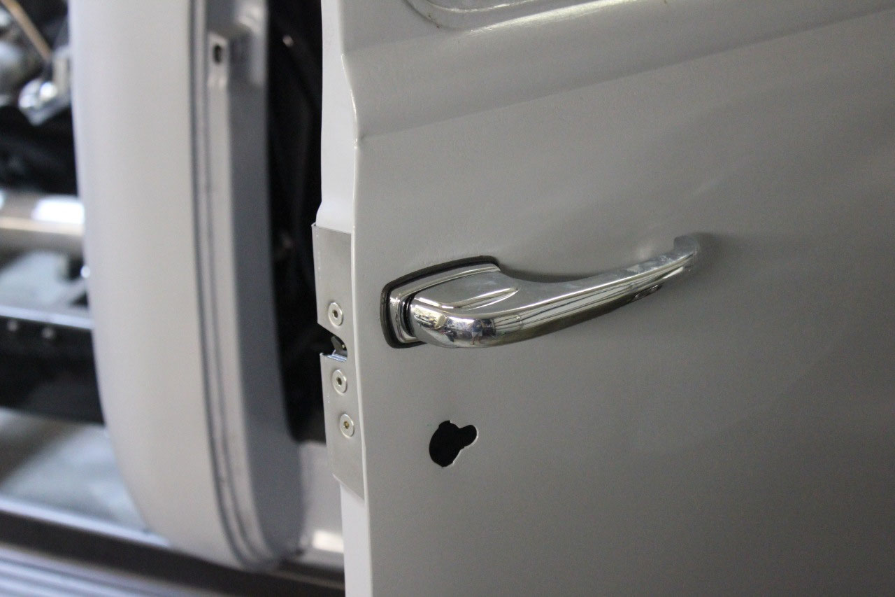
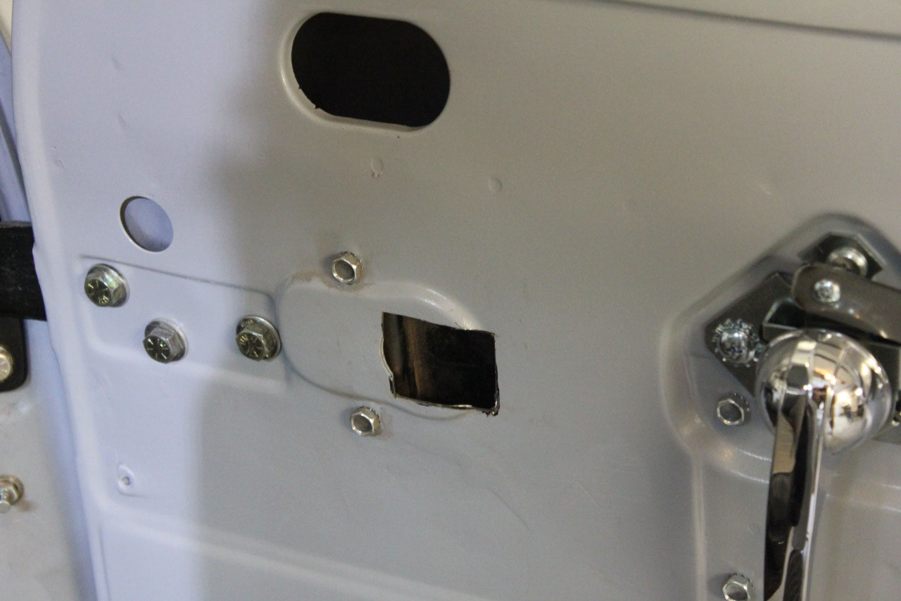
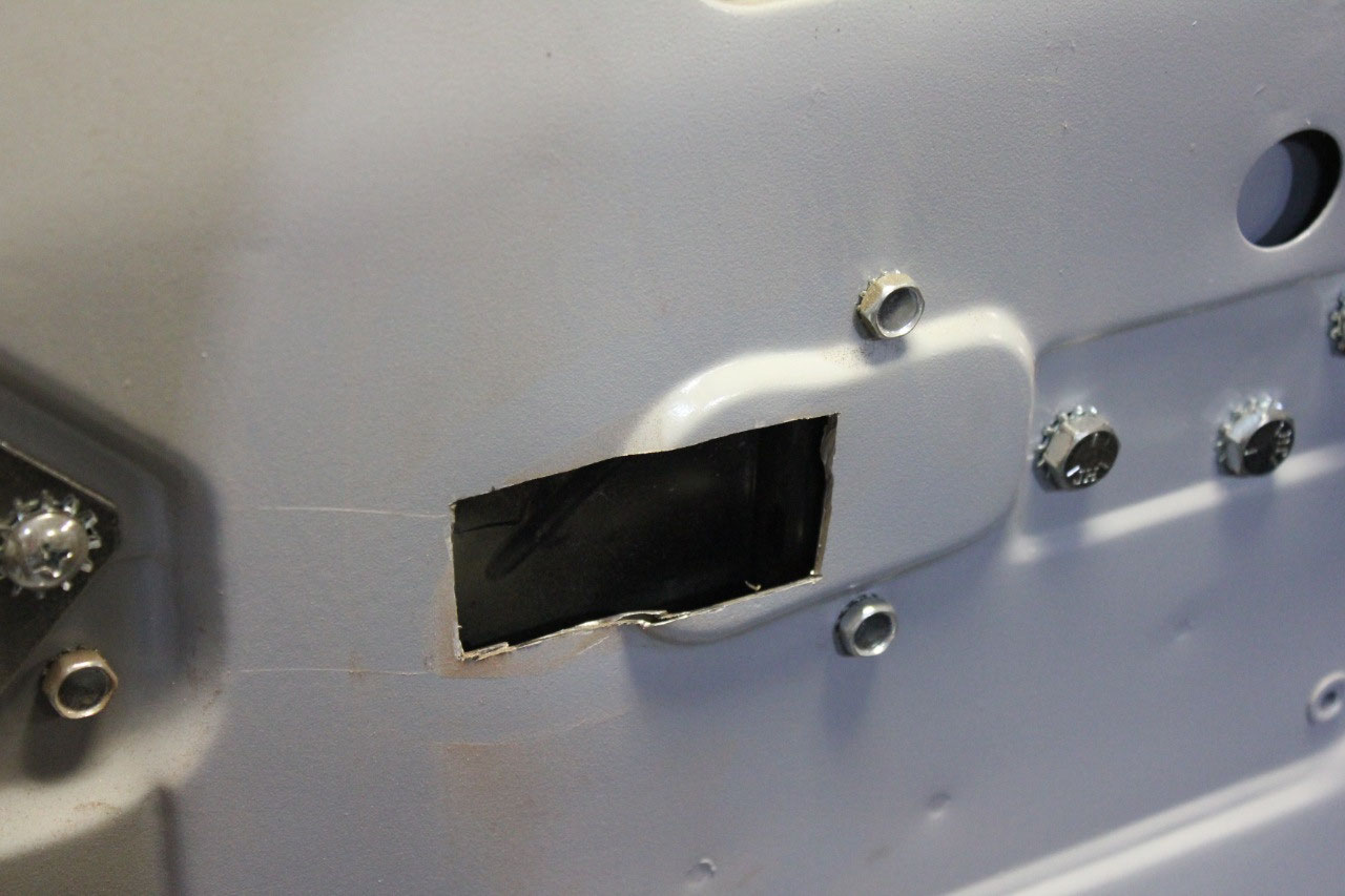
Enter Altman Easy Latches made by Trique Mfg. These replacement latches update the terrible
original design to a modern bear-claw type latch. The only problem is that you have to cut a
big hole in the door to install them, and you lose the capability to lock the
doors from the inside by pushing the door handle forward. These trucks originally do not have the
typical lock button of this era, but instead locked by pushing the interior
door handle forward.
The other
interesting thing is that there is only an outside key lock in the PASSENGERS
door! The driver’s door cannot be
unlocked from outside. Evidently the
engineers of the day decided it was unsafe to open the driver’s door in
traffic, and that the driver should unlock the passenger’s door and scoot over
into the driver’s side. It seems odd to
us now, but iof you watch old 50’s TV you often see people entering and leaving
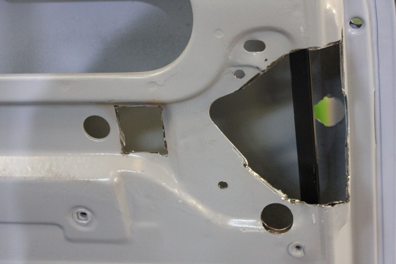
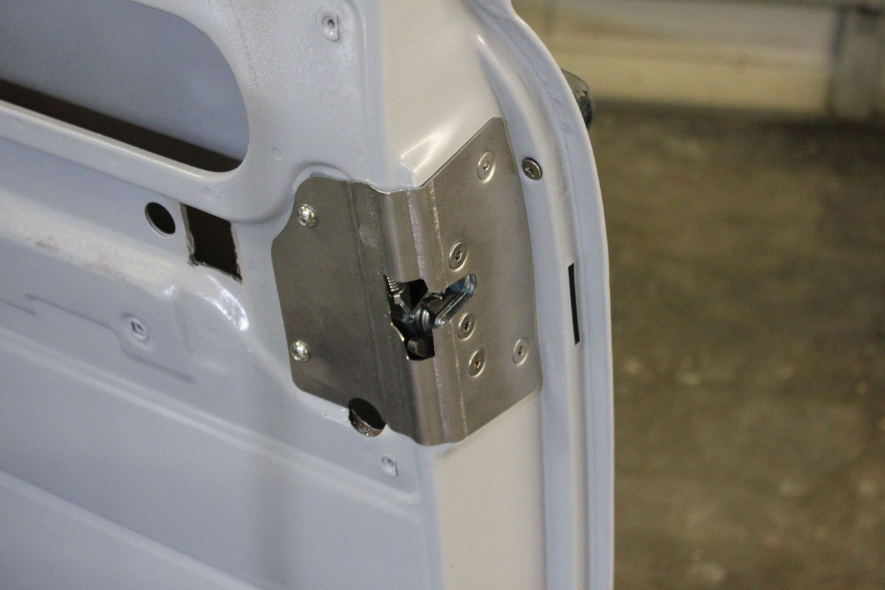
from the passenger’s side when parked in downtown traffic. In any case, Trique also sells a custom
bracket for installing power door lock actuators with instructions on how to
make them work with Altman latches.
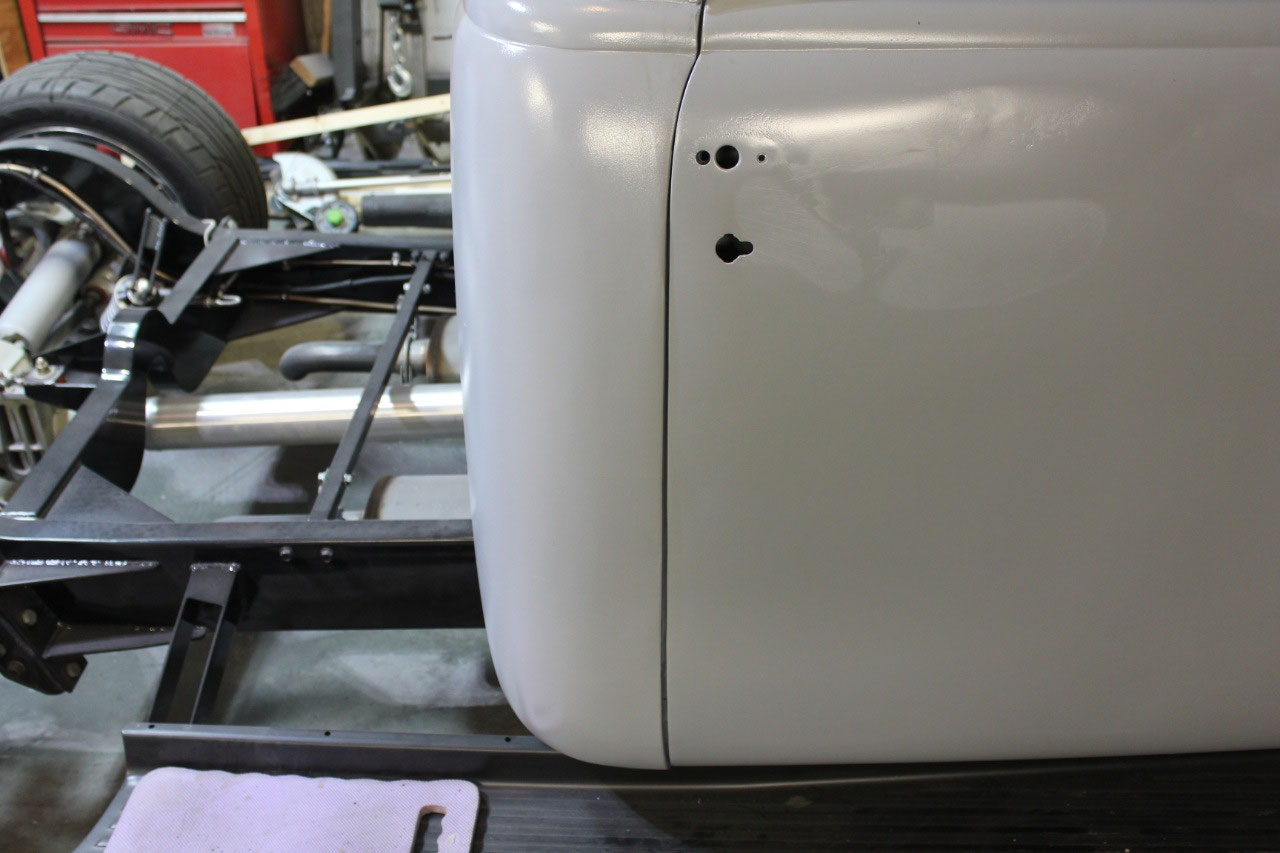
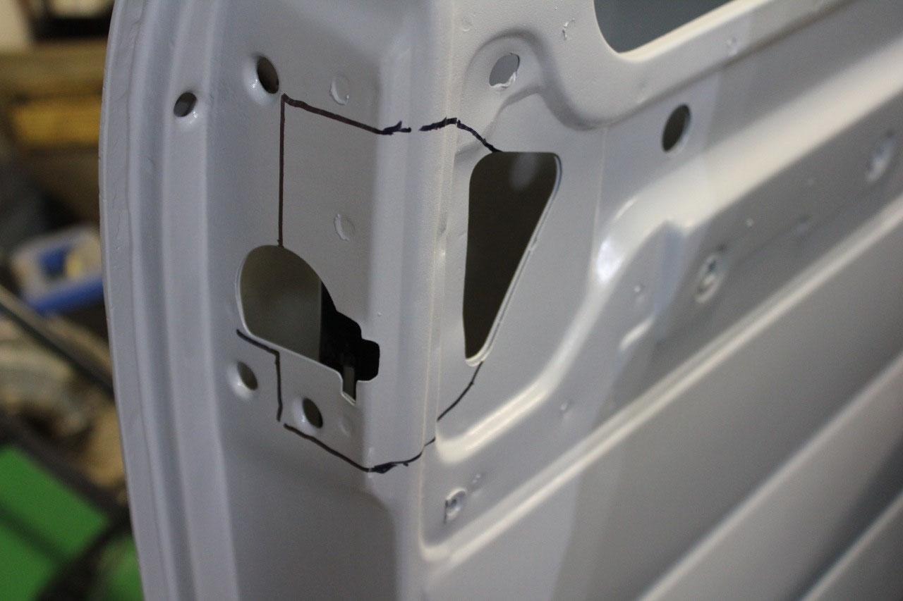
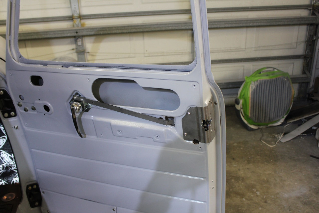
So, following the template, I cut the big holes in the door
and mounted the passengers latch. I
could not believe how well it worked. On
the first try, I just closed the door easily and it latched perfectly without
slamming at all! I went ahead and
installed the driver’s side and it almost worked as well. The Latch pin in the can was just a hair too
high, and the door was rising up slightly.
I just elongated the hole for the pin mount by about 1/8” and it now
works perfectly! The only other
modification different than the Altman instructions was at the place where the
door handle rod attaches. The
instructions had me installing the pivot bold with the nut on the outside
scraping the inside of the door panel. I
found a low profile bolt and a low profile locking nut and was able to install
it with the nut on the inside, so it should fit better on the door panel. Next step was to install the passenger’s
lock, which mostly involved trimming the lock rod length substantially. It was an easy cut, but the replacement
Chinese lock rod broke the first time I tried to use the lock. I drug out the original lock rod, did the
same modification and it worked just fine.
I just needed to wait a few days for a new lock retaining clip to
arrive, as I had somehow lost the original that came with the truck.
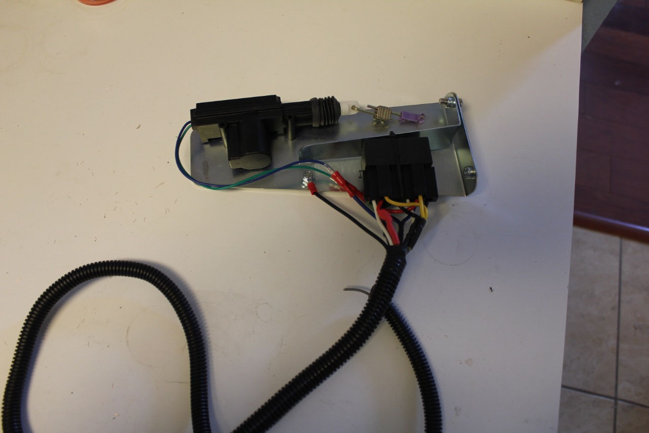
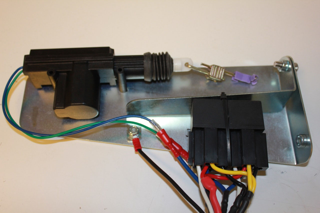
Now it was time to install the power door lock
actuators. This turned out to be a
little more difficult than it should have been.
I installed the actuators, bent up the rod per the instructions, drilled
the holes by the template and it all fit great.
I hooked it up to the alarm signals, tried the fob and it worked
perfectly. But I had forgotten all about
the lock/unlock switches I had intended to install on the doors
themselves. I thought I was being
clever when I installed the Viper 451M module as part of the alarm to provide
the reversing relays to run the actuators.
That’s great for the alarm, but not so good for the door switches. This meant I would need to run a new pair of
wires to run the 451M module from the door switches and I didn’t want to run
more wires through the driver’s “A” pillar.
So in the end, I decided to just add an additional reversing relay set
inside the driver’s door and to use the 451M module output to drive these
relays. It wasn’t difficult, and it was
easy enough to hang the relays off the driver’s door actuator bracket. Problem solved!
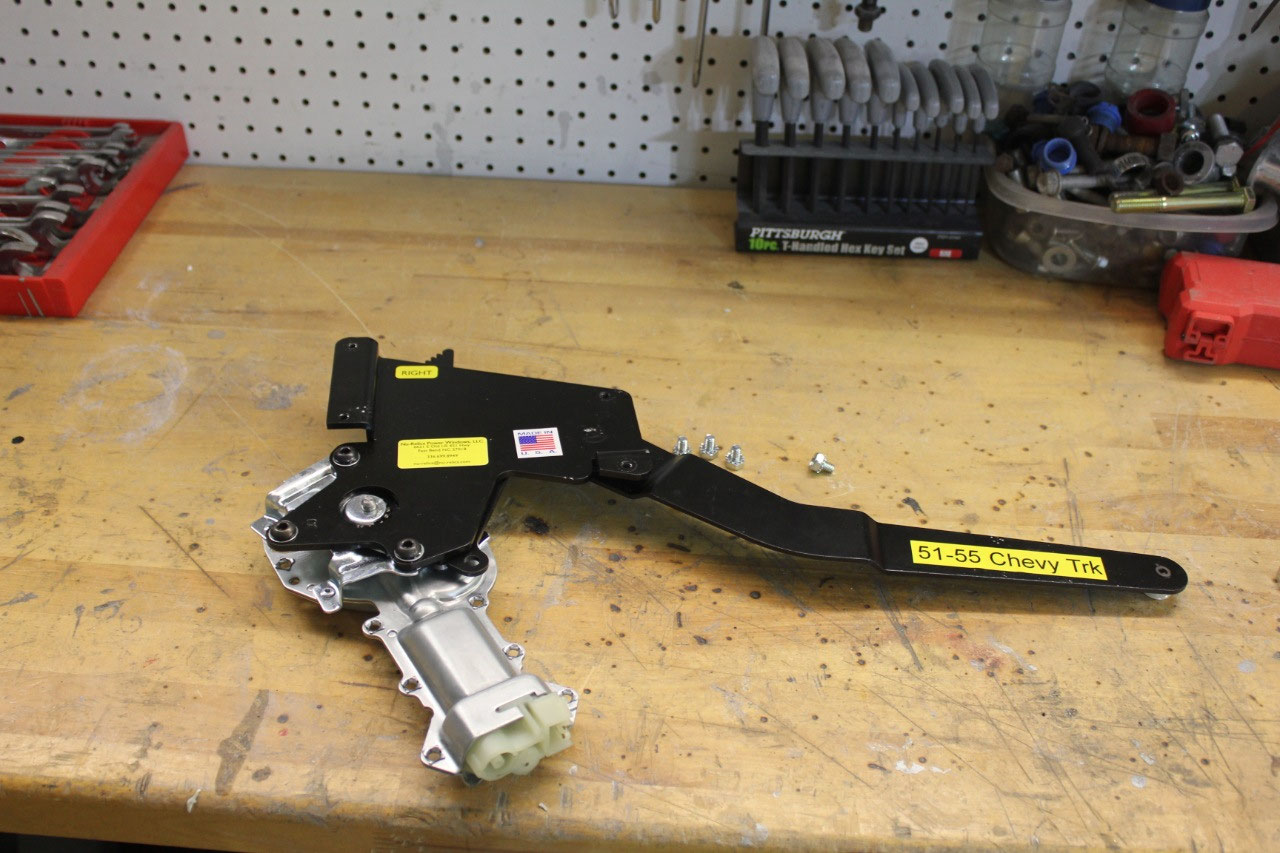
And now a word about switches. Now that the power door lock problem was
addressed, it was time to pick power window motors and power window and power
door lock switches.
I looked at all the
power window manufacturers and figured out Nu-Relics were probably the
best. In addition, the power window
motors were just a bolt-in and wouldn’t require any additional
modifications. Nu-Relics offers several choices
for switches, but I decided to use the classic chrome GM style used throughout
the 70’s and 80’s with a double switch on the driver’s door and a single switch
on the passenger’s door. I also wanted
the matching power door lock switch with the word “Lock” on either the top or
bottom to indicate the direction to lock or unlock the doors. The driver’s and passenger’s lock switch
would lock and unlock both doors.
So I ordered the Power Window motor kit from Nu-Relics and
they looked great. The power door lock
switches are easy to find, but the mating connectors are specialized and
difficult to find. But I found a set by
A1Electric. When the A1 Electric kit
came in, they were not really Power Door lock switches, but were power window
switches wired to operate power door locks so they are not marked with the lock
position.
So I ordered a pair of real
power door switches and hoped to use the connectors and wiring. Unfortunately, the pin spacing on power door
lock switches is slightly different that power window switches so they wouldn’t
fit. I ended up taking the switches themselves
apart so I could swap the bezels. I now
have what are ostensibly power window switches with power door lock bezels that
will operate my power door locks correctly and are marked with the “lock”
position.
Finally, when the Nu-Relics Power Window kit came in, there
were small metal clips that are folded over at the opening in the door panel
upholstery that the switch will snap into.
The A1Electric power door lock switch kit didn’t come with these clips. Unfortunately, these are also difficult to find,
but I finally found them at Original Parts Group. I finally have the switching I wanted, but it
shouldn’t have been this hard!
Cutting the holes in the door for the power window switches
was not difficult, though I did need to trim the long pin on the window
switches to get clearance.
I understand
this is not unusual. I installed the
power door lock switches in the door panel above the power window switches in
an existing relief hole for the vent window spring adjusting nut.
Running the wires for the power door locks and power windows
turned out to be much more difficult than I imagined. The recommendation by Nu-Relics was to attach
the wires to the lower hinge and follow them into the door. While this will probably work for the 3-wires
for the power windows, there just wasn’t room for the 7-wires necessary for
power windows and power door locks. Most
modern cars anticipate some sort of wiring coming in the door and provide a
relief between the door and the jam to run these wires. Not in 1951.
There is very little room between the door and the jam and the geometry
doesn’t lend itself well for a retracting conduit between the hinges. The best place, with the best geometry is
below the bottom hinge, and there are a few examples of this on the internet. The other problem with most of these are that
they are fairly small with a typical 5/16” opening.
Great for 3 or 4 wires, but 7 would be tough.
All of the wires are 16 gauge and would simply not fit. I ended up routing the wires under the dash,
through the kickplate and out the bottom hinge (I had to remove the doors and
hinges to route the wires) I then kept the 12V power wire at 16 gauge reduced
the power window wires to 18 gauge, and reduced the power door lock wires to 20
gauge as they passed through the conduit.
I then returned them to 16 gauge inside the door. It’s not perfect, but it should be fine. Before I removed the doors and hinges, I
drilled a 1/8” pilot hole from the inside of the door that went through the
door and into the jam. After the door
and hinge were removed, I widened the hole to 3/4“on the jam and 13/16” on the
door. I trimmed the power window
connector so it would fit through the 13/16” hole. Unfortunately inside the door at the conduit,
there is a ¾” nut. The power door lock
weatherpack connectors will fit through the nut, but the power window connector
will not.
It’s only 3 pin, but will have
to be unpinned and repinned to get the nut removed before the door can be
removed.
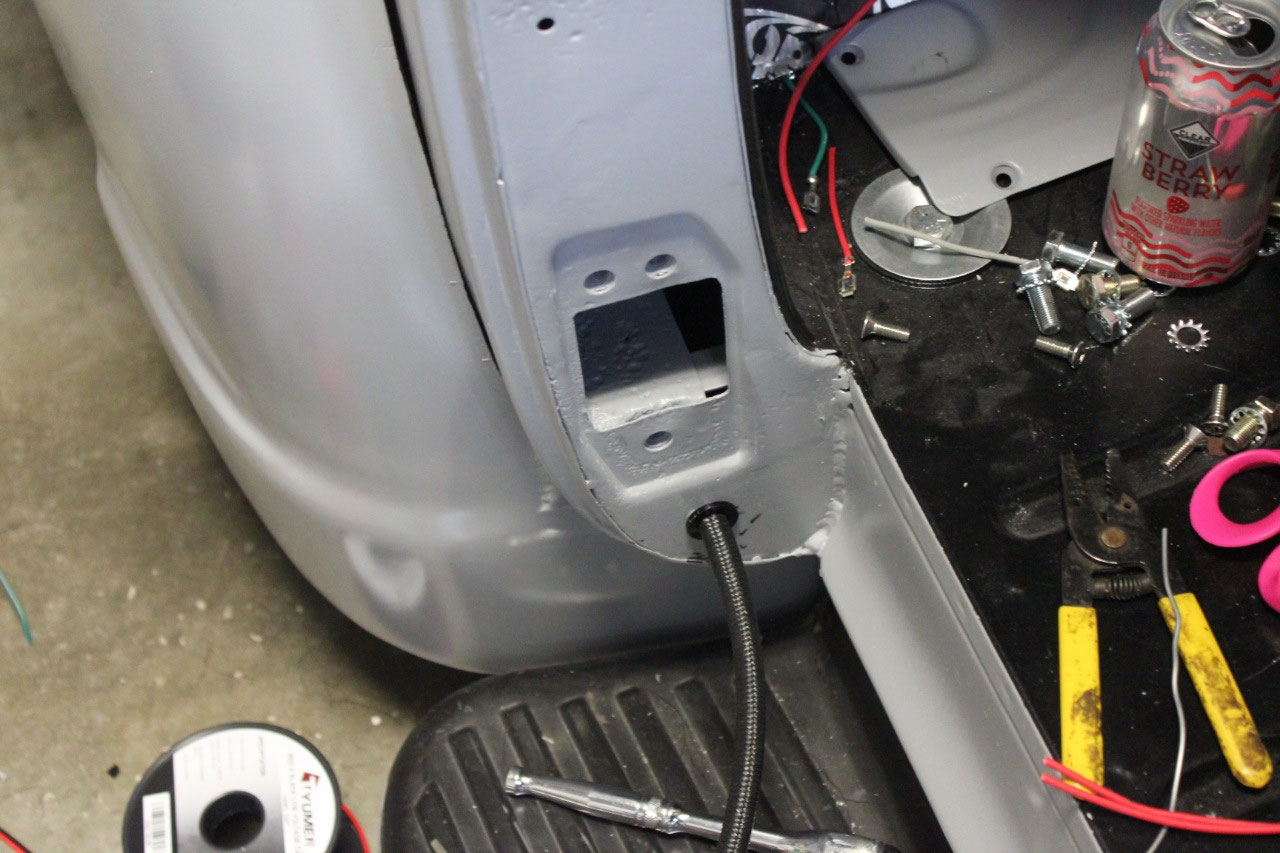
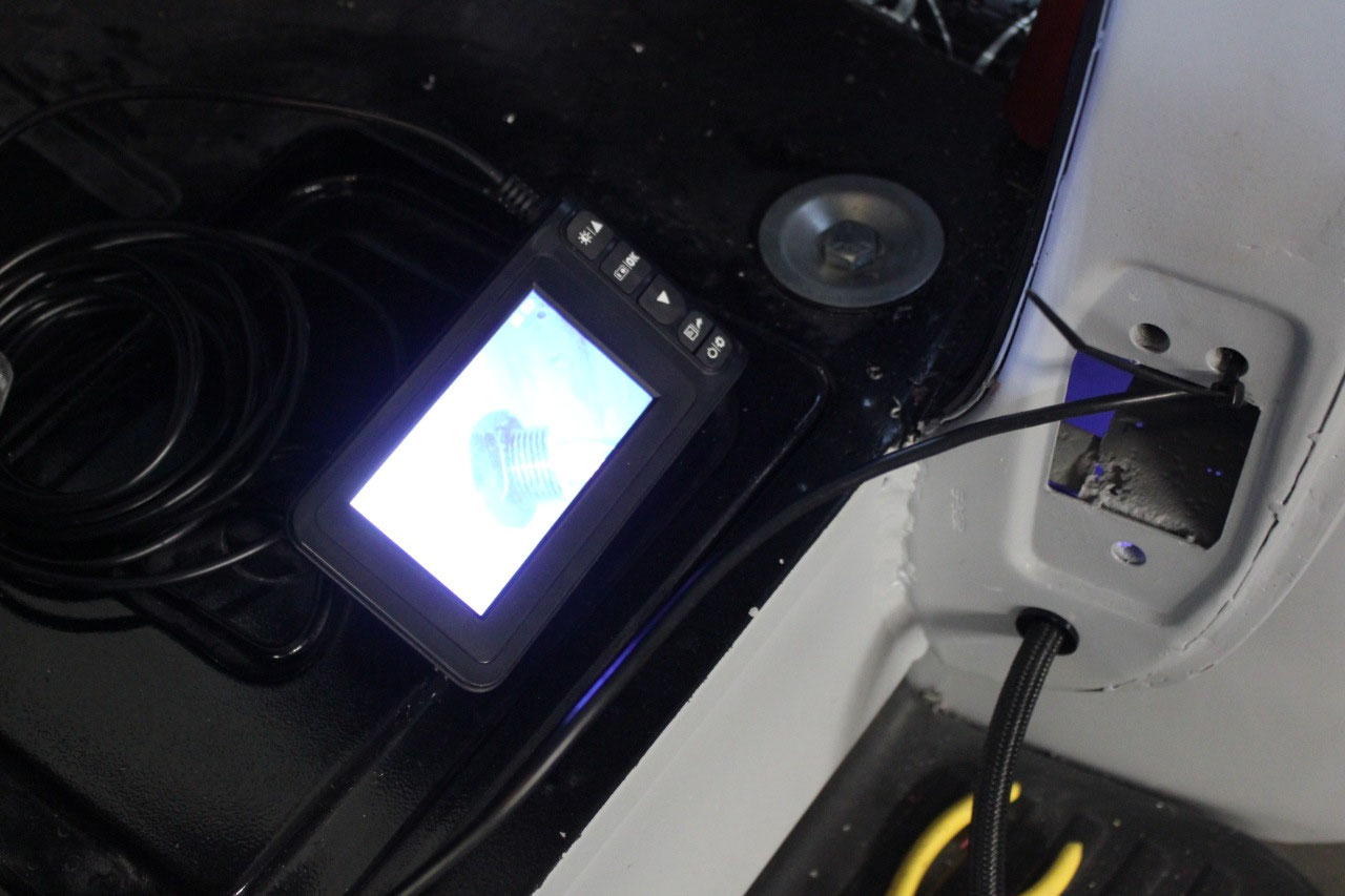
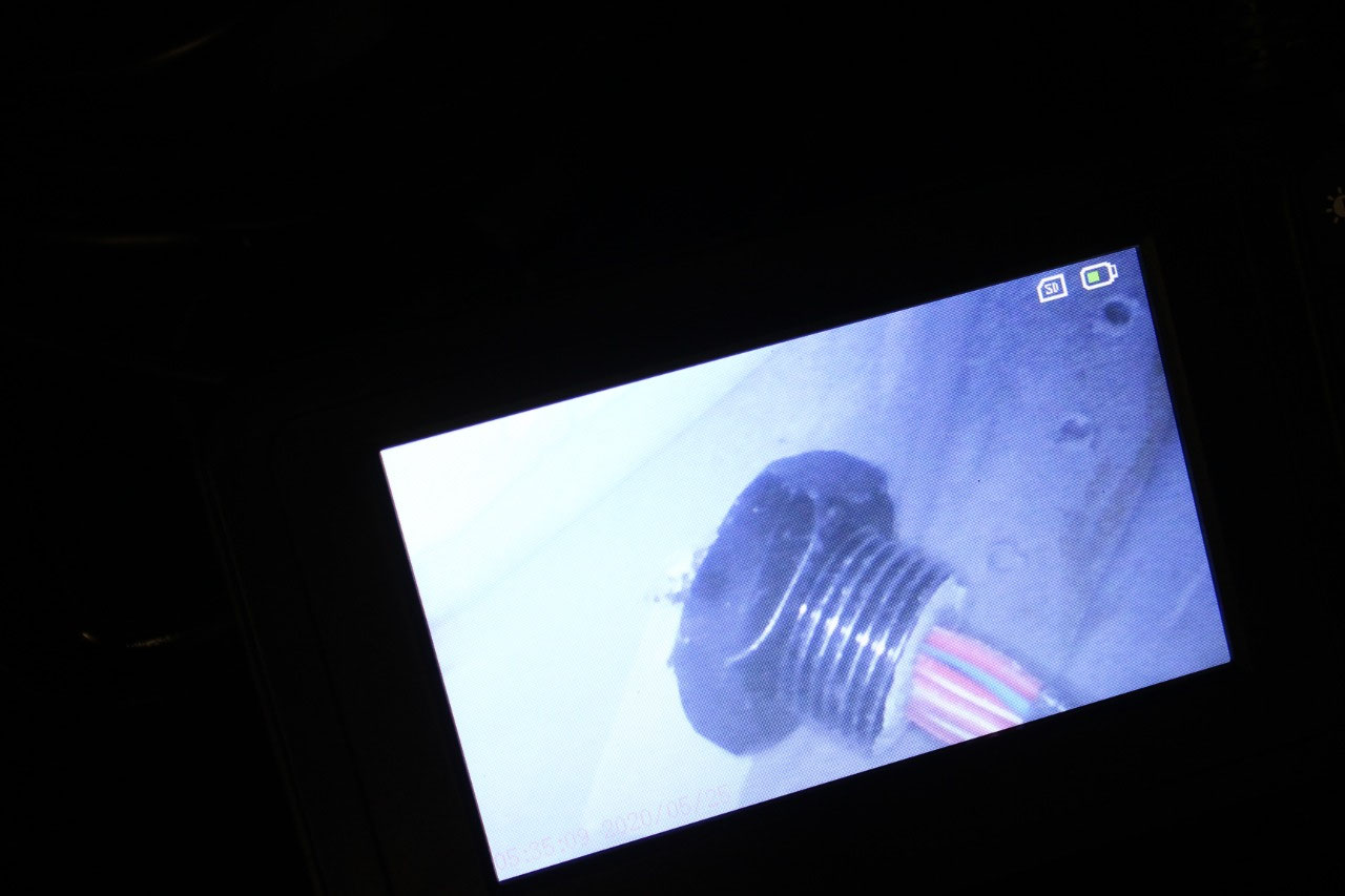
The other difficulty was installing the nut on the conduit
on the cab side behind the hinge. I was
able to slip the wires through the nut before routing them through hole and the
conduit. Luckily, I have an endoscope camera,
so I was able to run the fibre through the hinge opening and manipulate the nut
with a small metal rod through the opening.
After several tries, I was able to install and tighten the nut, and hold
the nut while turning the conduit with channel lock for the final twist. I hope it’s tight enough!
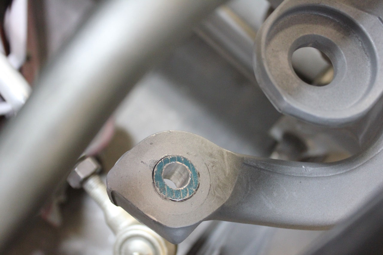
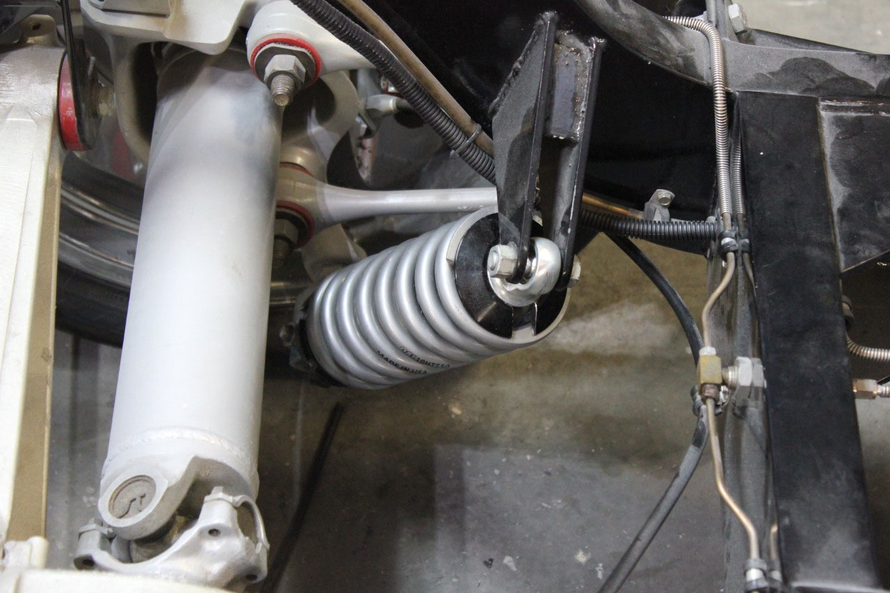
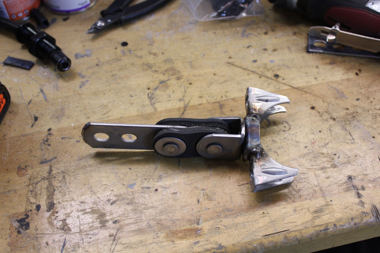
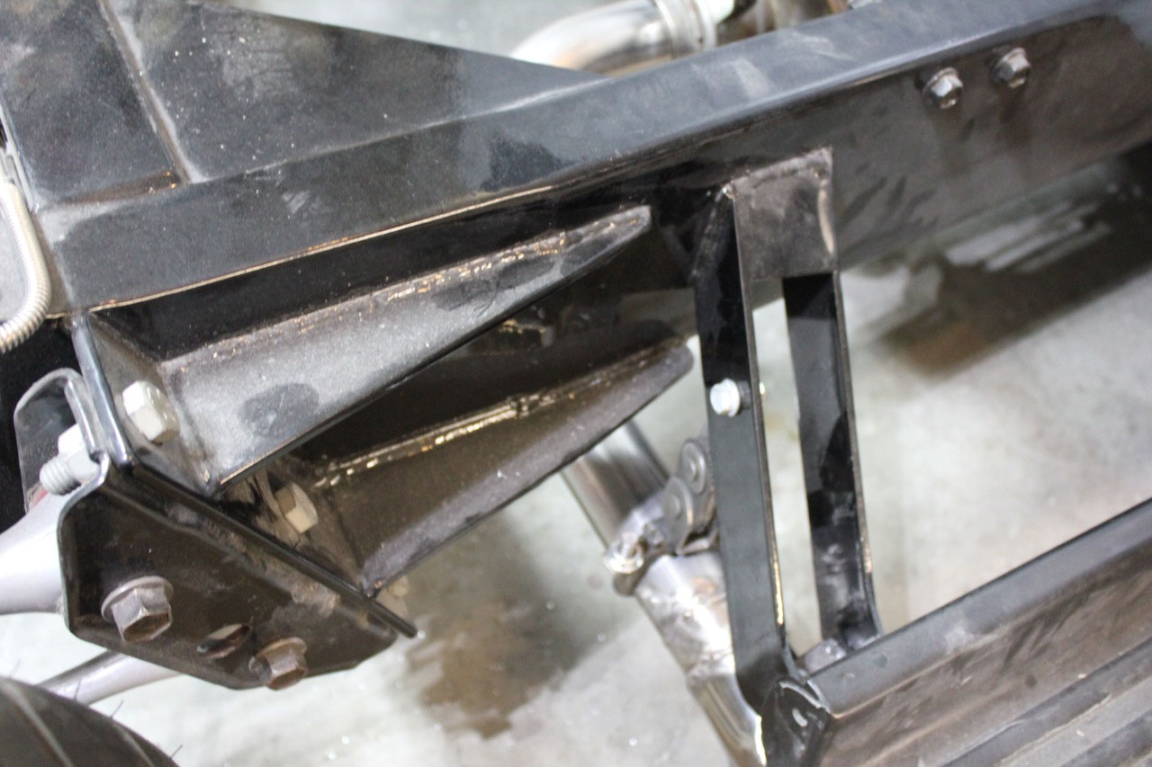
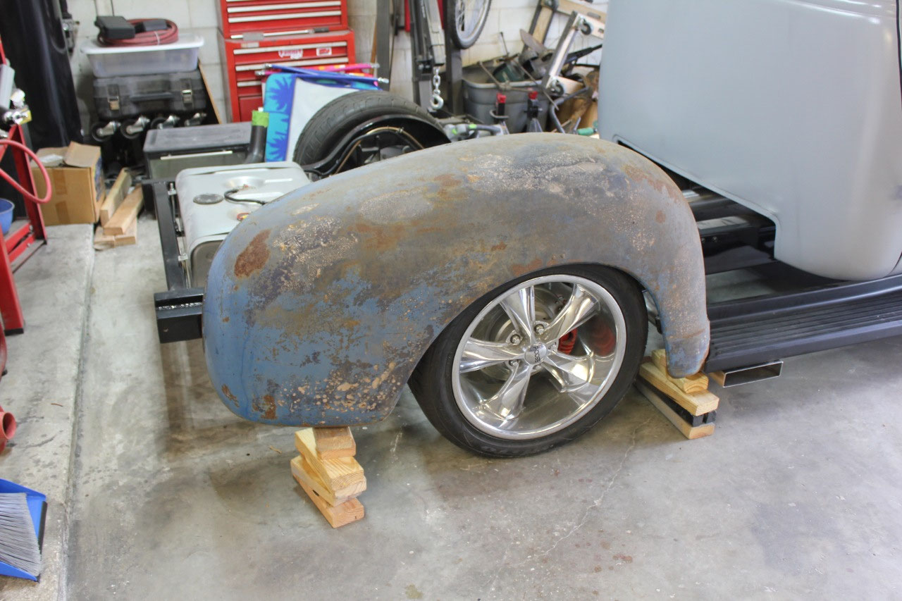
The next project had been lying around for over a year, and
I have never got around to fixing. At
the rear axle, the tie rods from the axle center section to the hubs are
adjustable in length for alignment.
These rods will interfere with the frame as the suspension is
compressed, so Randy had me install a “flip kit” to reverse the tie rod ends
and gain clearance.
I was still
concerned with clearance at full compression, so I found some tie rod extenders
for an F100 Ford truck that lowers the tie rod to prevent bump steer. These look perfect for my application to gain
the clearance I need. The only thing I needed to do was to replace the tapered
bushings from the flip kit with 7/8” aluminum round stock and drill the hole
for the mounting bolt. I also needed to
modify an 18mm open end wrench to gain access to tighten the nut. It all worked out great, and I have plenty of
tie rod clearance.
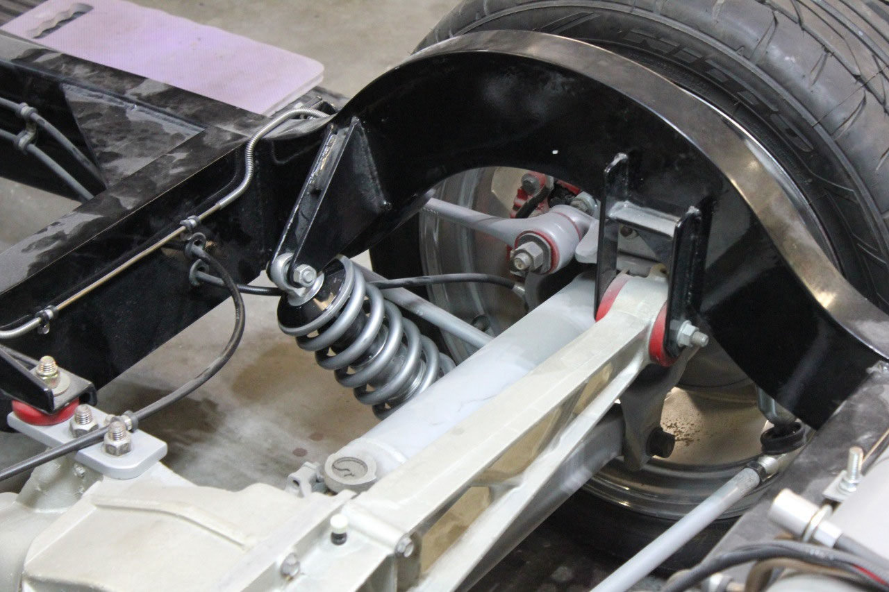
While I was working at the rear, I decided to go ahead and
tackle the rear springs on the coilovers.
When I bought the frame, Randy at Rockabilly Fabrication recommended 350
lb/in springs for the front and 175 lb/in springs for the rear. The fronts seem to be about right, but the
rears are just too weak. I tried
adjusting them up but they just seem way off. The rear is still lower than the front and the
bed is not installed yet! I replaced the 175 lb/in with 250 lb/in a
while back and they didn’t seem to help much.
I went back and looked at some older pictures from Rockabilly
Fabrication and realized that earlier versions of this frame had the rear
coilovers nearly vertical. On my frame,
they are tilted in at 45 degrees and tilted forward 45 degrees which if my high
school vertor math is correct means I am probably losing about half of the
strength due to the angle. I had a pair
of 550 lb/in springs that I had bought a long time ago when I thought the
fronts may be too weak and decided to install them on the rear to see how they
work. They work great! They might be a little too heavy as the rear
is now slightly above the front, but I will use them for now until the weight
of the bed is installed.
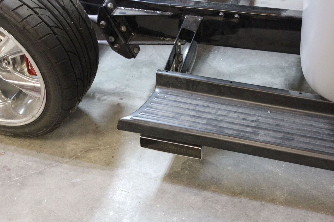
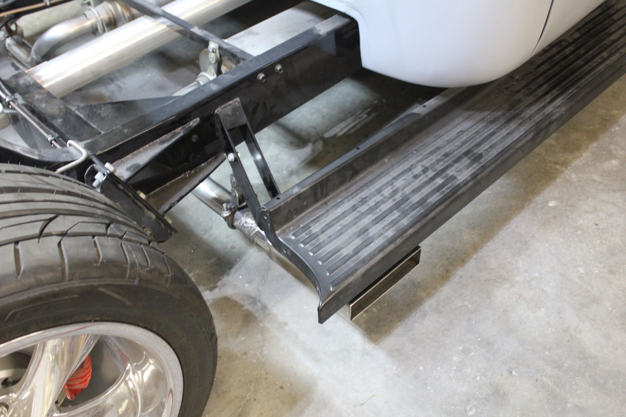
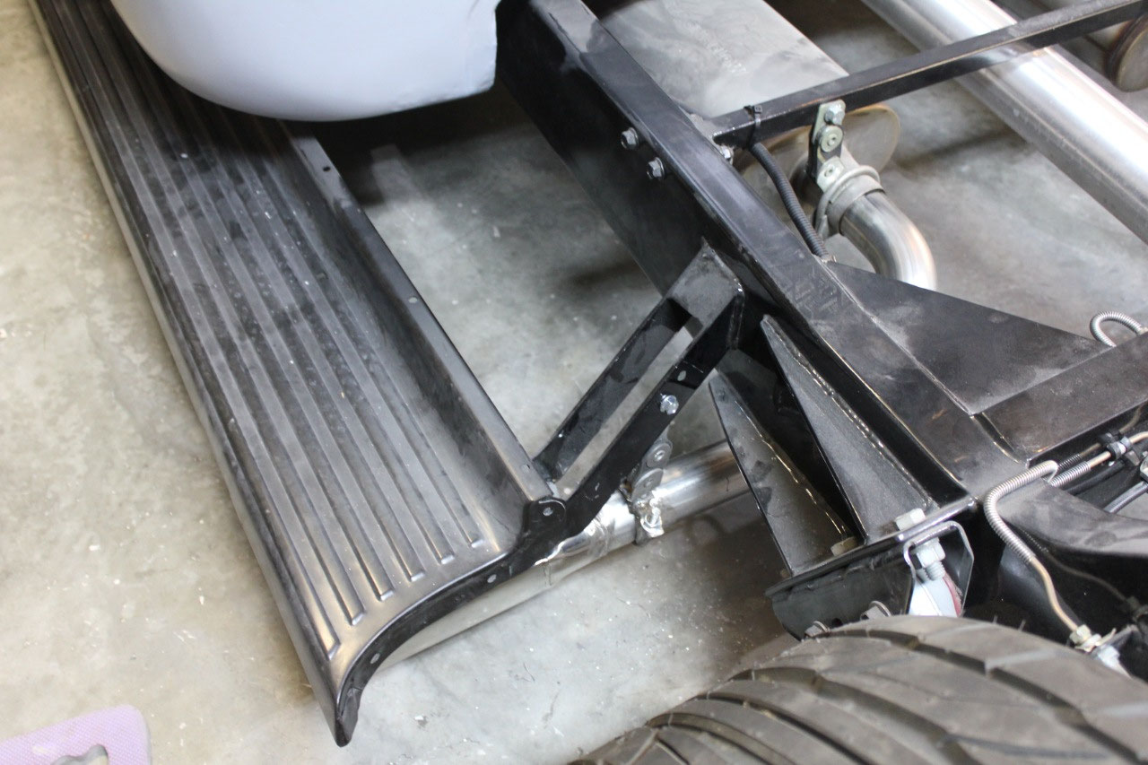
The other task that has been hanging around for a while is
the completion of the exhaust. I had
toyed with the idea of routing the exhaust between the bed and the chassis,
over the rear suspension and out the back, but it was just too complicated and
would look to hokey. Instead I will just
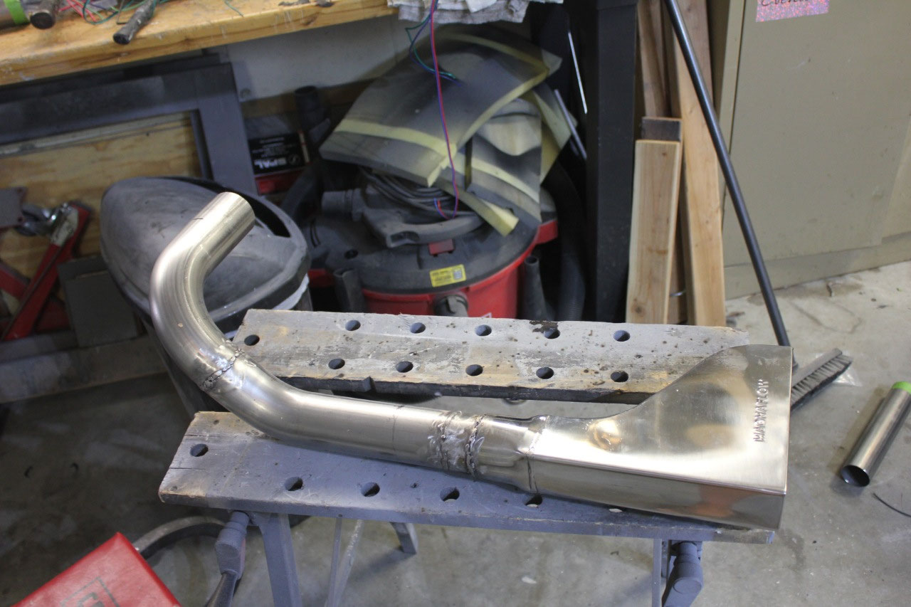
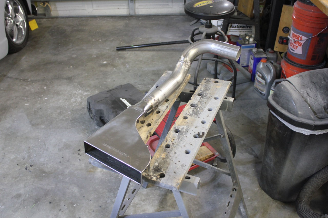
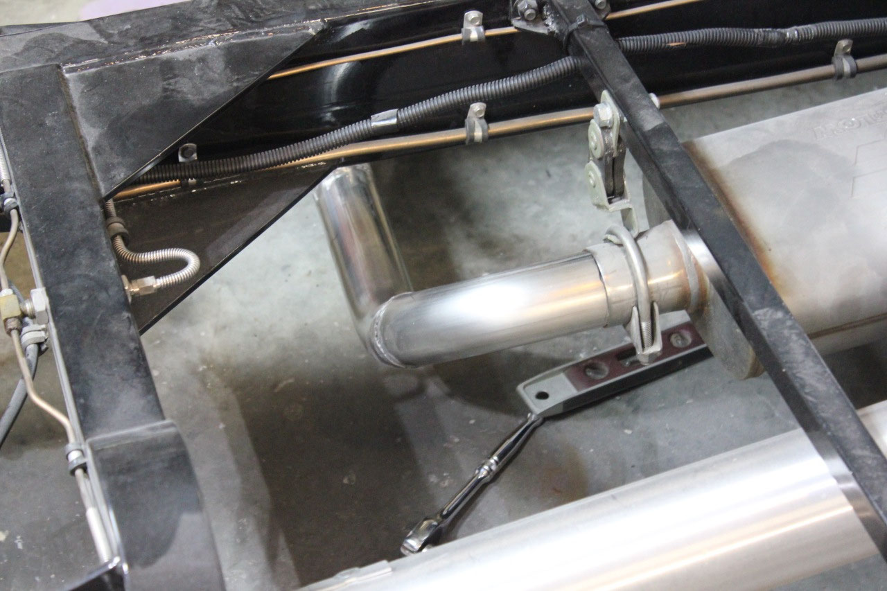
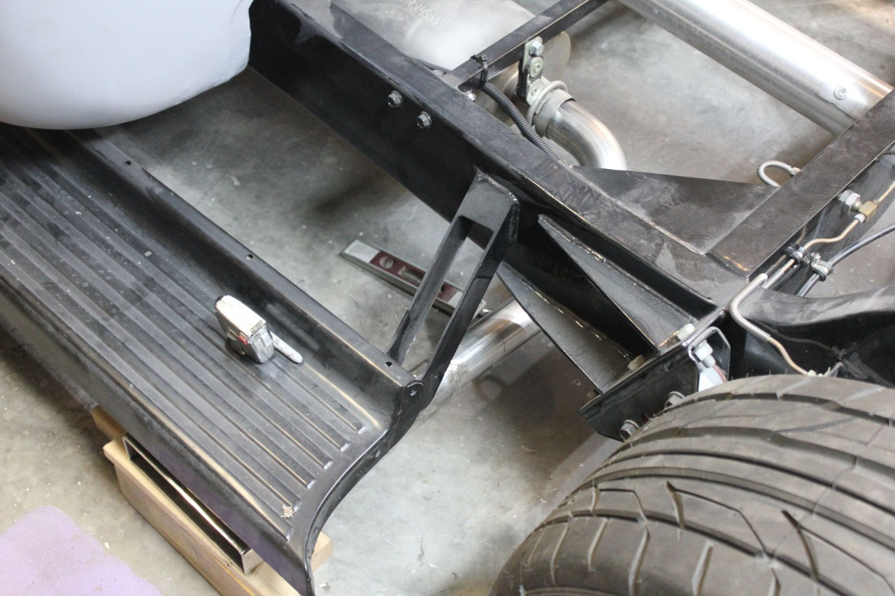
use rectangular outlets under the running boards.
I have seen people cut the rectangular
outlets into the running board, but unless you have air bags and can lay the
running boards on the ground, I don’t think they are necessary.
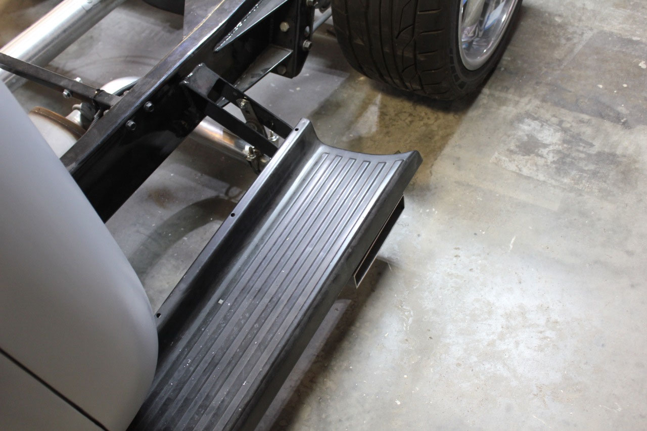
So I changed out the wire in my MIG for stainless wire,
bought some 2-1/4” 90 degree and 45 degree bends and welded up the rest of the
tailpipes. I had to do a little welding
to make up the hangers, but they tailpipes tuck in well. The only odd thing is that since the previous
tailpipes pointed down, there was some muffling by the garage floor. Now that they point sideways, they exhaust
echoes in the garage and is much louder.
I’ll have to wait to see how it sounds out on the road!
At this point, the only projects left in the cab are the
glass installation, alignment of the front sheet metal (which may involve a
modification to the radiator) and cleanup of the door gaps. The interior just needs door panels,
headliner, and carpet. I was originally
going to attempt my own door panels, and I bought the ABS plastic door panel
bases.
I just want to use some excess
seat cloth, stitch it up vertically to match and glue it to the base. I thought I had access to a sewing machine
and was going to give it a shot. But we
donated our sewing machine to Goodwill long ago, so I started looking for
someone local. I found Xtreme Auto
Upholstery just a few miles from my house, brought him my ABS Plastic bases,
some cloth, and the panel clips for the power switches and he said he could do
it in 2 weeks for $100. Sounds like a
good deal to me!
Rather than start with the glass as the next project, it’s
finally time to address the bed. Last
week, I ordered the parts for the bed from Mar-K in Oklahoma. It’s all new Made in America sheet metal,
with a few custom options. The bed sides
will eliminate the stake pockets, since I don’t need them. The front bed panel will have an embossed
Chevrolet bowtie. The tailgate will have
a single pushbutton latch and stainless scissor brackets to eliminate the
chains. The bed wood will be upgrade to
cherry and the bed strips will be polished stainless with hidden fasteners. It’s time to head to the beach for a week
vacation and hopefully the bed will arrive soon after we return!


2025-05-22