 Orlando, Florida, United States
At some point, it occurred to me that the radiator core
support was not perpendicular to the frame.
From what I could tell from pictures, the core support does pitch
forward, but the angled mount on the radiator causes the face of the radiator to
be perpendicular to the frame. So I put
a level on the frame and jacked up the rear of the chassis so that the frame
rails were level. This allowed me to
place a level on the radiator face, and add shims under the core support to
make the radiator vertically level and therefore perpendicular to the
frame. Of course, when I did this, I
lost a little of the space between the waterpump and the radiator and the fan
no longer fit.
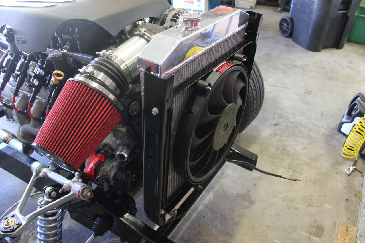
So now it was back to the drawing board on the fan. I had always been concerned with the 16” Spal
fan, that it only had 1500 cfm and various articles had called for something
more like 2500 cfm. Since I did not have
room for a puller fan, it was time to look for a pusher fan that I could locate
in front of the radiator.
Most of the articles
recommended Derale Fans as a more robust version and I found just what I wanted
at Summit Racing. The Derale 16917 is a
17” 1800/2500 cfm dual speed fan that is only 2.65” thick and is designed to be
mounted either in front of the radiator as a pusher or behind the radiator as a
puller. Sounds perfect! So while I was waiting for the fan to come
in, I decided to tackle the radiator hose routing.
The upper hose was fairly straightforward, and I bought some
2” pool vacuum flex hose that I could use to mock up the path. The upper went fine, and the flex hose could
easily be bent to follow the path. The
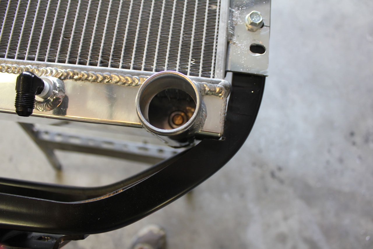
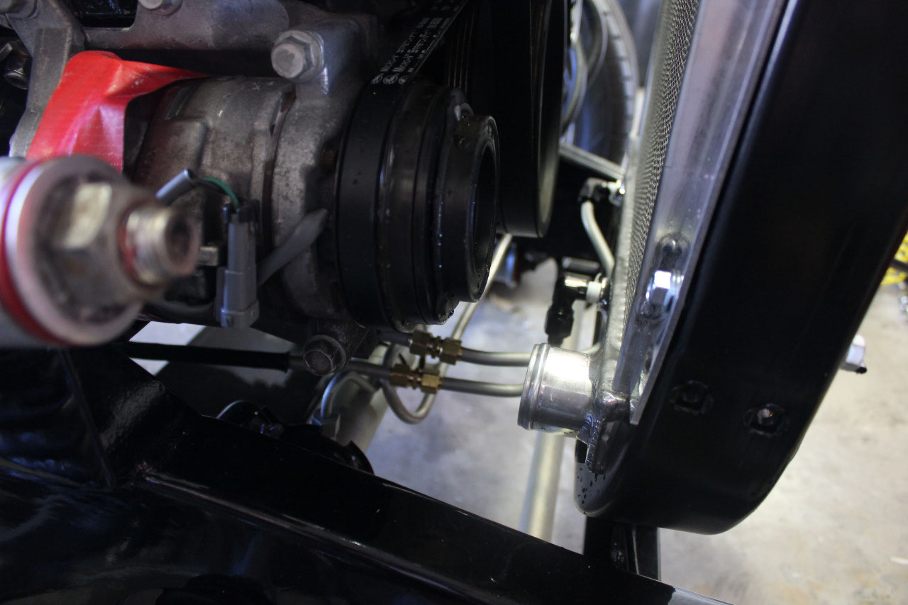
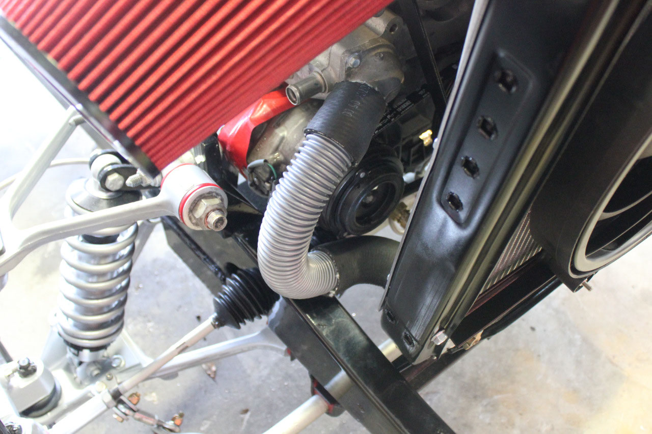
lower hose was a problem. The lower
radiator outlet points directly at the A/C compressor clutch and needs a quick
90 degree turn. I bought a lower hose
with a 90 degree bend so I could cut off the 90 degree and transition from the
90 degree hose to the pool vacuum flex hose.
It sort of worked, but the 90 degree elbow was very close to the A/C
clutch. I decided to take the radiator
to a local radiator shop and see if they could install a 90 degree elbow.
They sent it out to their fabricator, and figured
out that it would be just too difficult and expensive to modify the radiator,
and that I should try some other solution.
I thought about sending the radiator back to the manufacturer for
modification, or ordering a new, modified radiator, but I suddenly realized
that if I just moved the entire radiator mounting to the core support down
about an inch, my clearance problem would be resolved!
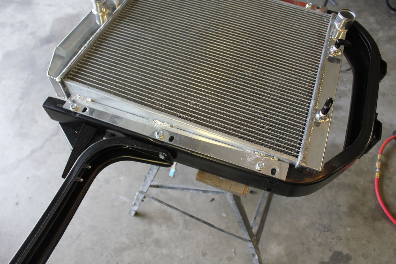
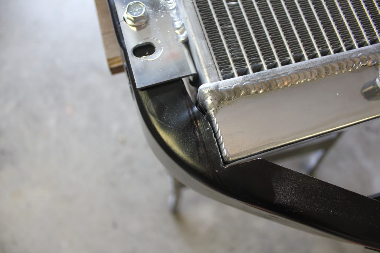
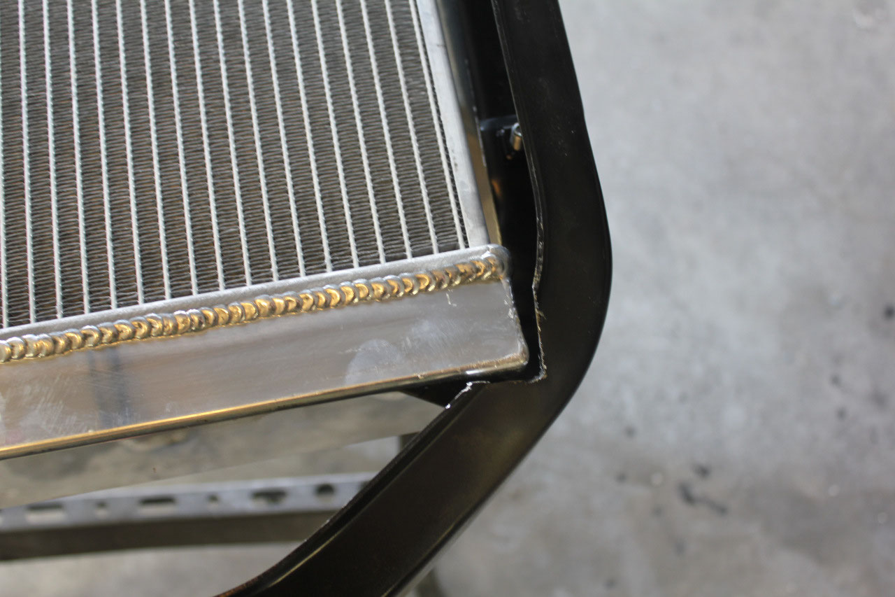
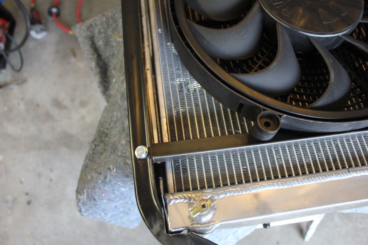
So I cut a notch into the base of the core support, and
drilled new mounting holes in the radiator angle mount and I was able to run
the lower hose 90 degree bend with plenty of room to spare. The 1 inch drop at the upper tank is barely
noticeable and should look fine when all the sheet metal is attached. I did have some concerns about structural
integrity of the core support as the notch cut in the support to lower the
radiator did compromise some of the strength.
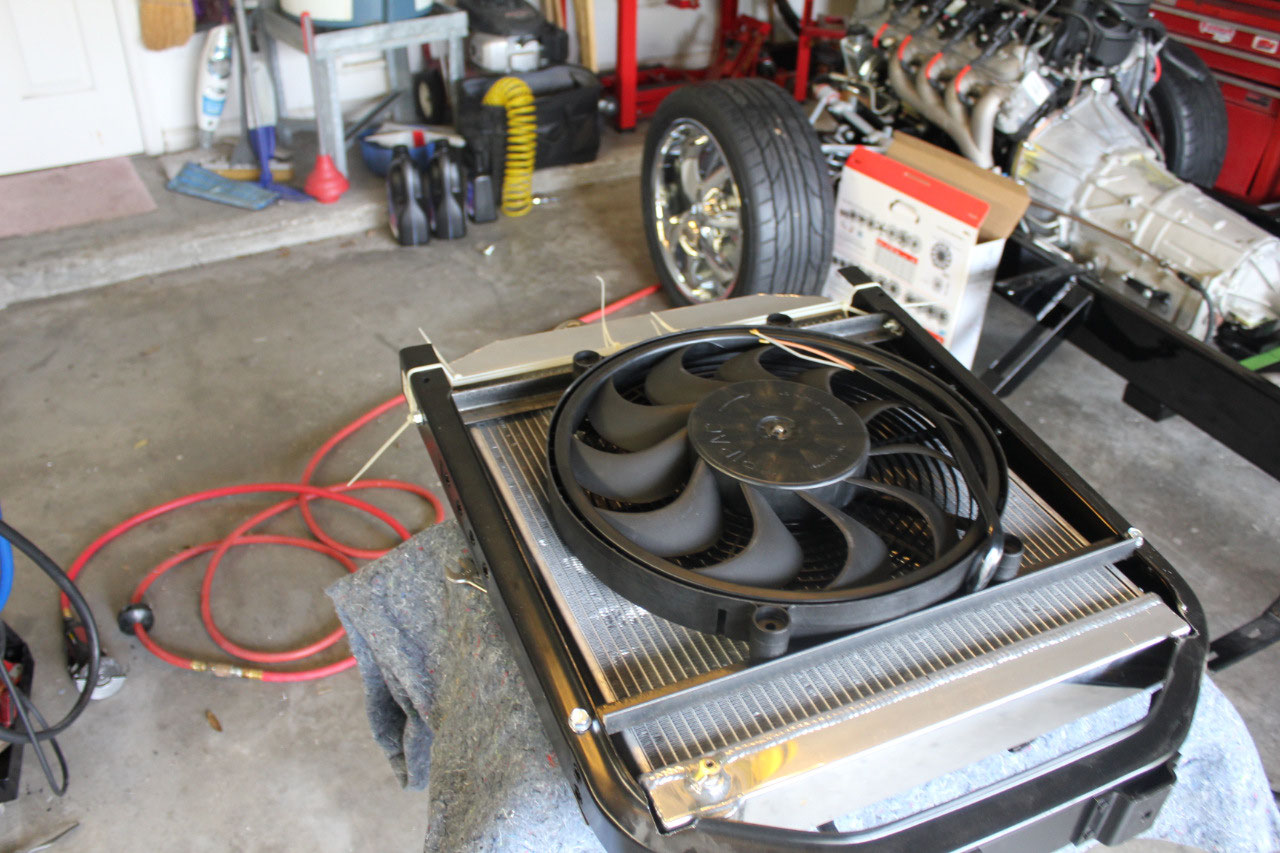
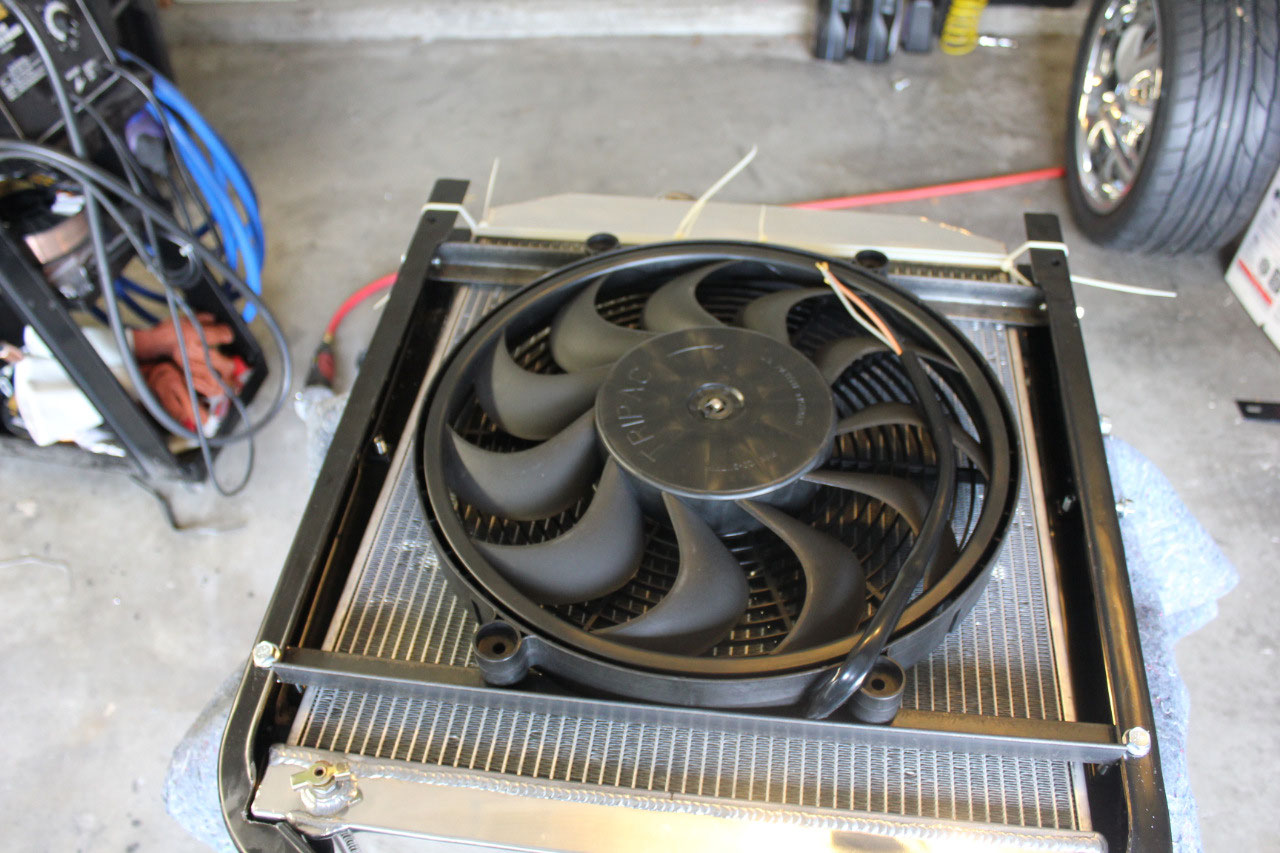
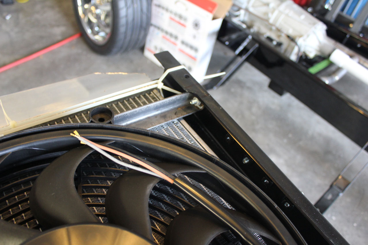
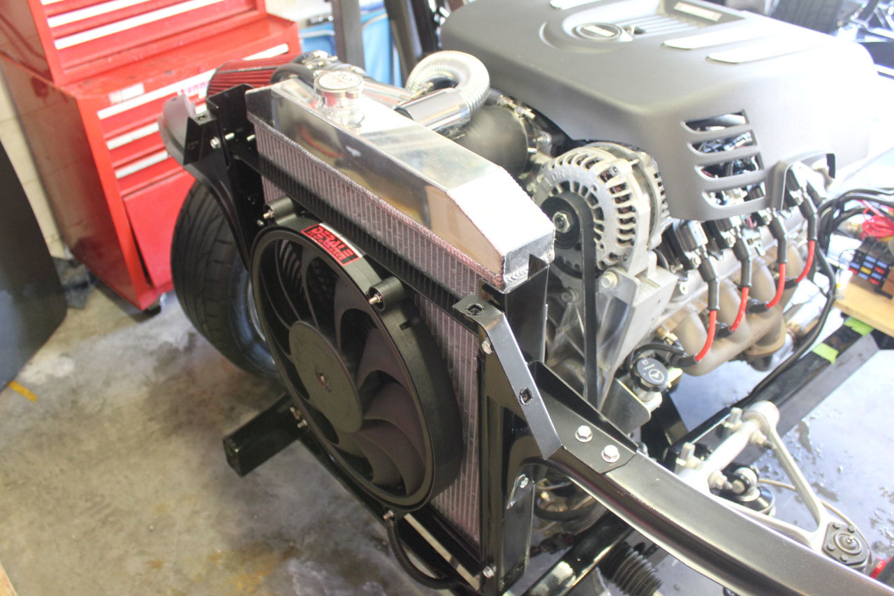
But the next step was to install the Derale fan and I decided to use a
pair of 1”x1”steel angle irons as a mounting bracket.
By the time I bolted the two 1”x1” angle
Irons to the core support to mount the fan, all structural integrity had been
restored.
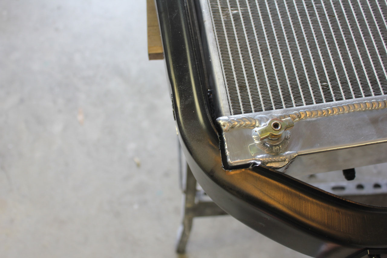
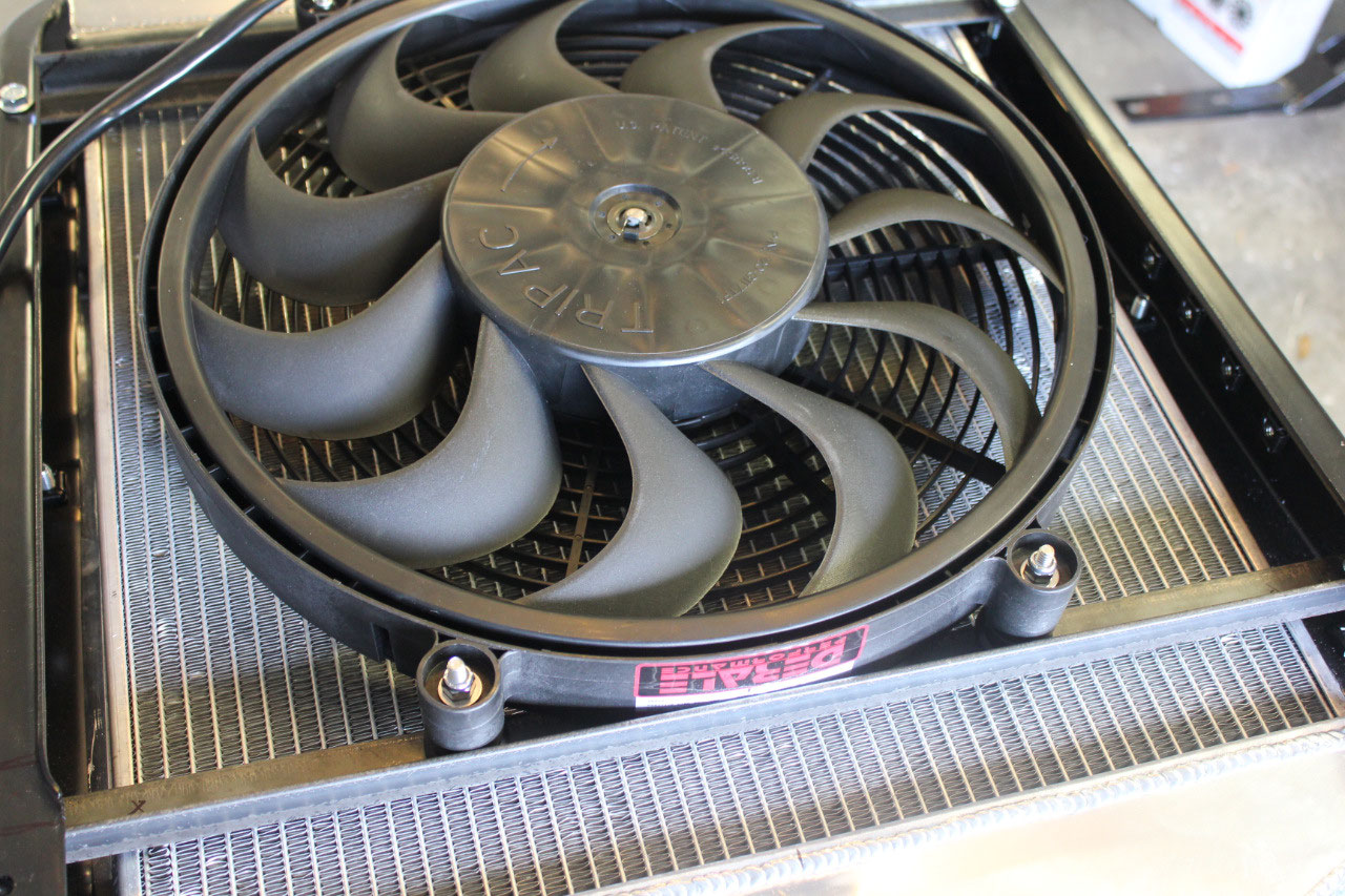
The fan mounting brackets came out great, and I had to use a
technique where I cut and folded over an end of the angle iron and welded it
together so I could install a bolt from the end. It’s all really strong and professional
looking, with the fan mounted to the angle iron with rubber insulators and I drilled
and filed the mounting holes square so I could use carriage bolts. It all looks great, and I should have plenty
of room to mount the A/C condenser in front of the radiator with the fan
sandwiched in between. Since this is a
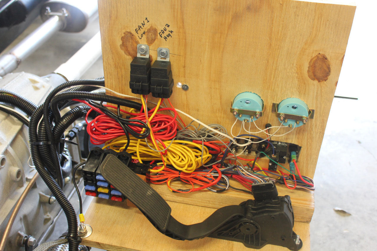
2-speed fan, and the ECM is programmed for 2 fans, the plan is to hook the 1800
cfm wire to Fan-1 and the 2500 cfm wire to Fan-2. This will take 2 relays, but it should make
for a reliable and quiet installation.
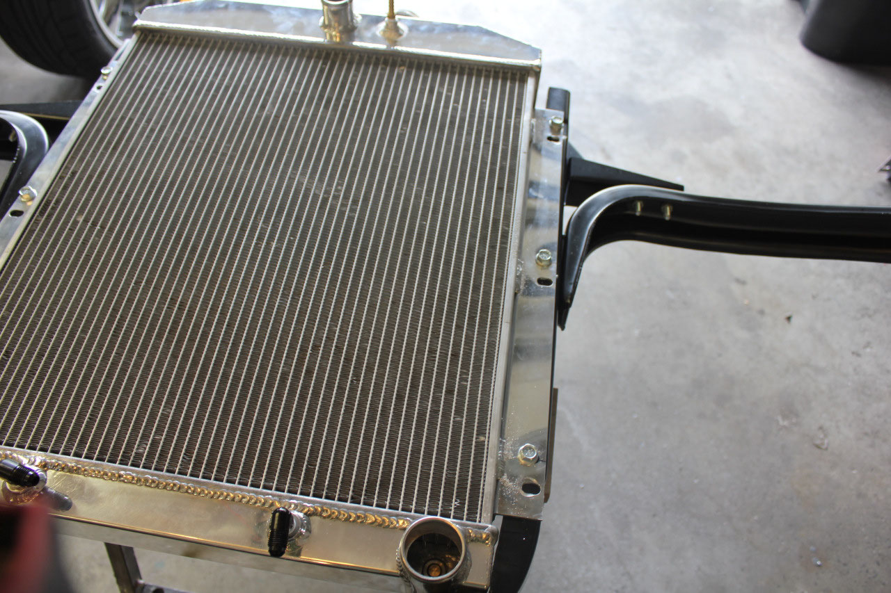
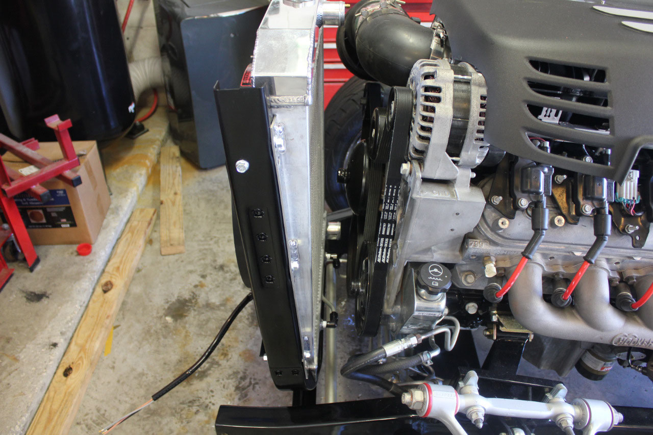
The radiator and core support were then disassembled and
everything was primed and painted gloss black to match the rest of the chassis,
and then reassembled for final installation.
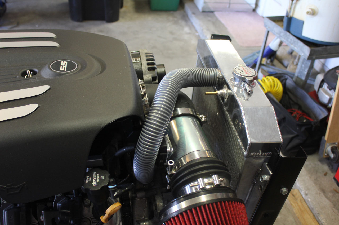
It all looks great! After looking
to see if I could find anything that looked worthwhile in a preformed radiator
hose, I decided I would use stainless flex hose with rubber couplings on the
end. The upper radiator hose would use a
chrome cover over the rubber coupling for appearance, but the others were not
readily visible, so an exposed rubber coupler would be fine. The
stainless flex hose is 1-5/8” OD, with the couplers set for 1-3/4”. There are rubber reducers to step down to
1-1/2” or 1-1/4”, so the upper hose used the 1-1/2” step down at the radiator
inlet and the 1-1/4” step down at the waterpump. The lower hose also used a 1-1/2” step down
at the water pump, and after several tries for the 90 degree coupler at the
lower radiator outlet, I settled on the 90 degree coupler designed for the
stainless flex, with the chrome cover removed for clearance. All in all it looks great! I also installed the heater hoses, making
them about 4’ long with a loopback coupler at the end so they should be ready
to remove the coupler and cut to length when the cab is installed.
I had originally connected a loopback hose across the
transmission lines to start the engine, but now that the radiator was
installed, I might as well connect the transmission lines to the radiator. I had some leftover steel line from the
factory fuel lines that came with the engine, and I was able to cut out some
pieces with the appropriate bends to connect between the cut off transmission
lines and the bottom of the radiator. A
couple of adapters and some quick work with the flaring tool, and the lines
dropped into place. Rather than get too
fancy with the coupling between the new lines and the existing transmission
lines, I just used brass compression fittings which worked just fine.
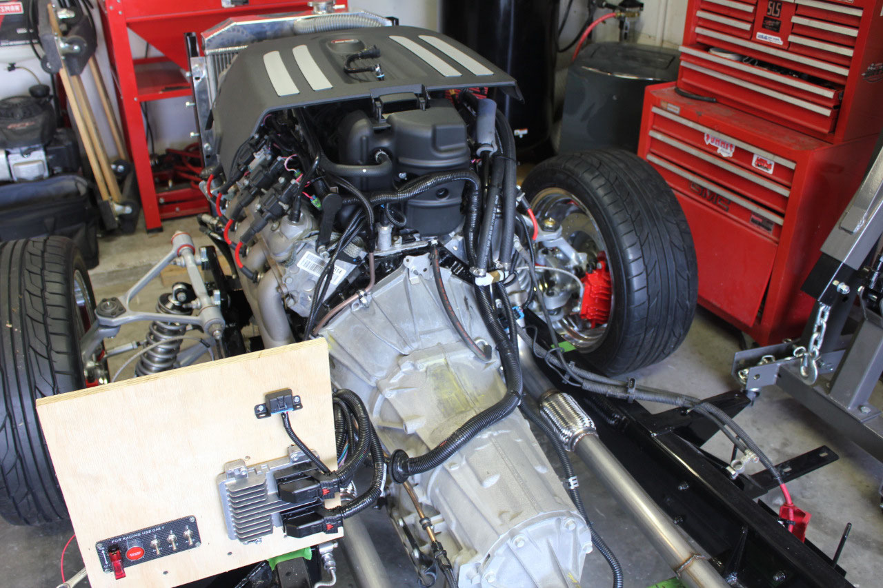
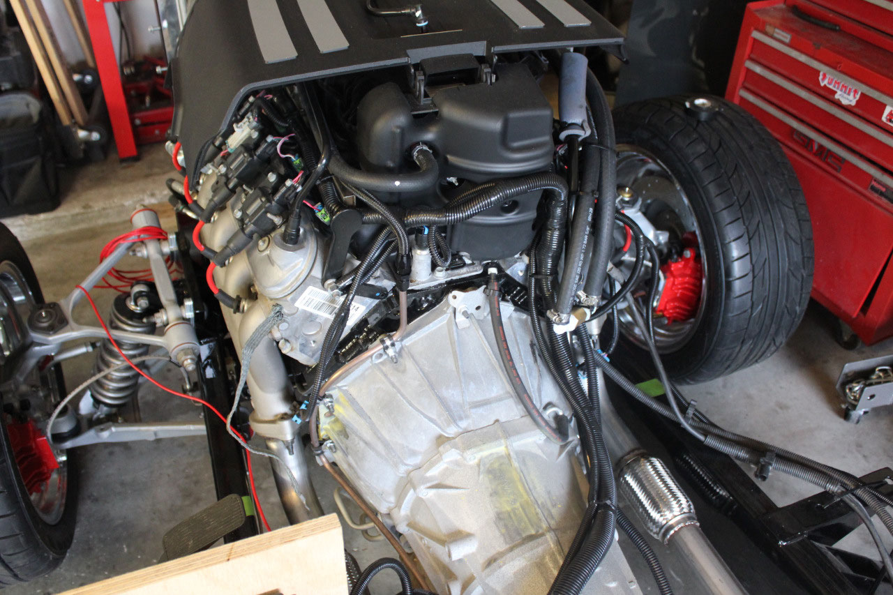
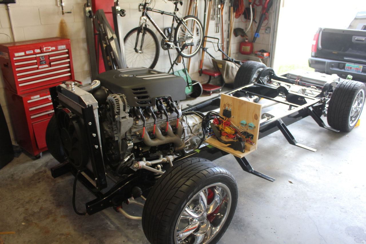
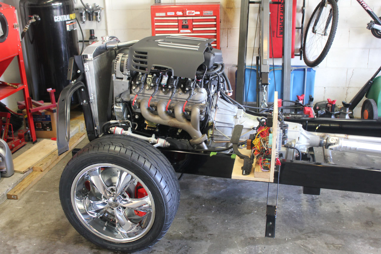
I was almost ready to fill all the fluids, when started
thinking about how to fire up the engine.
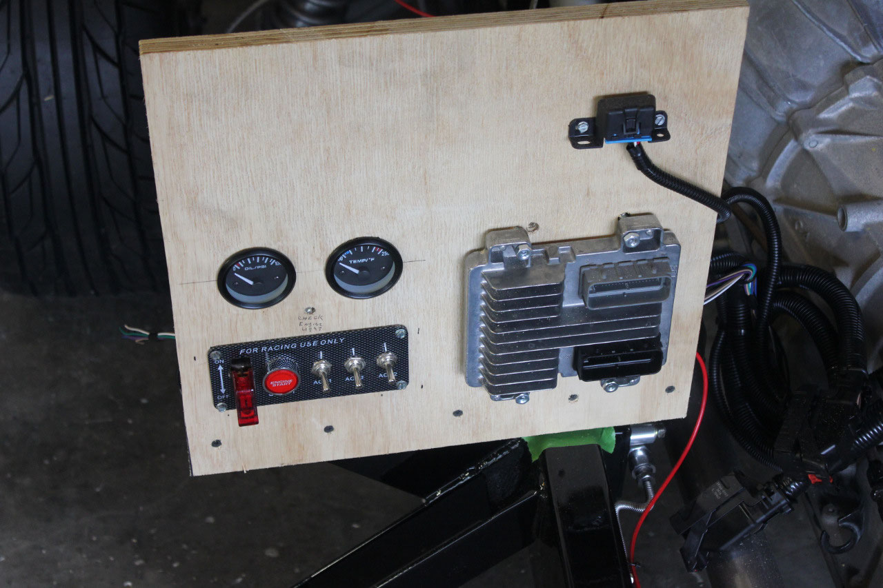
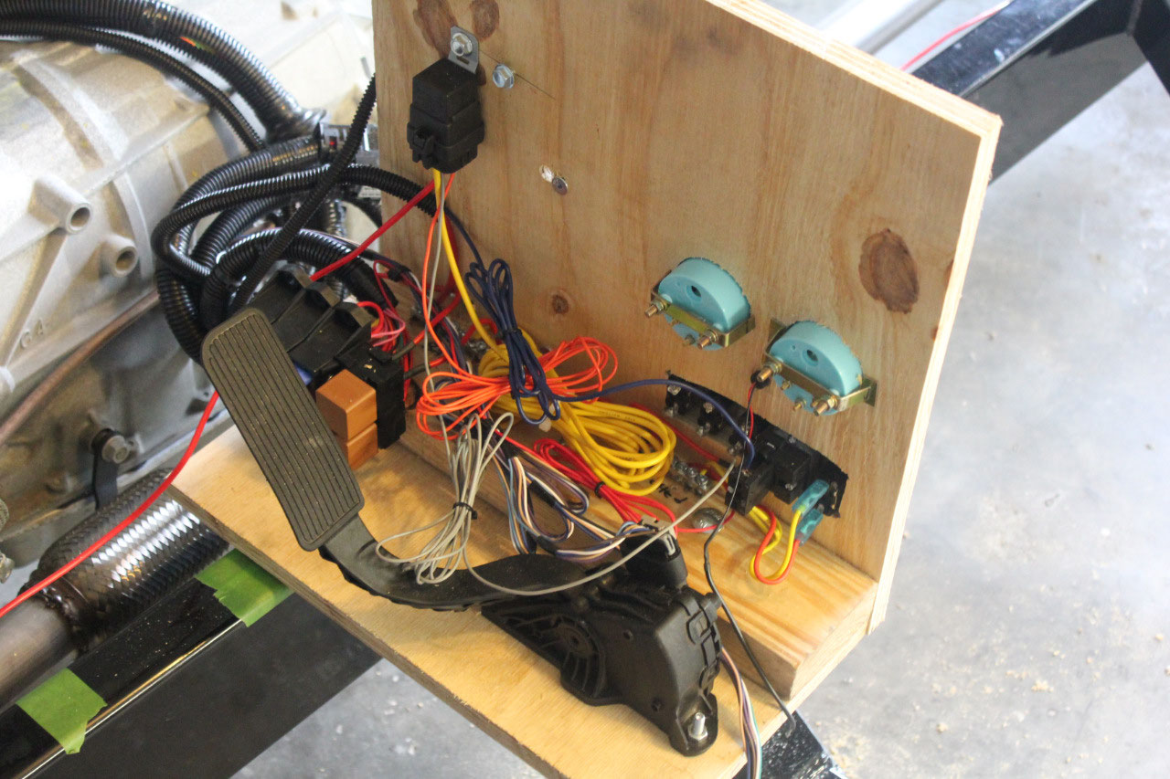
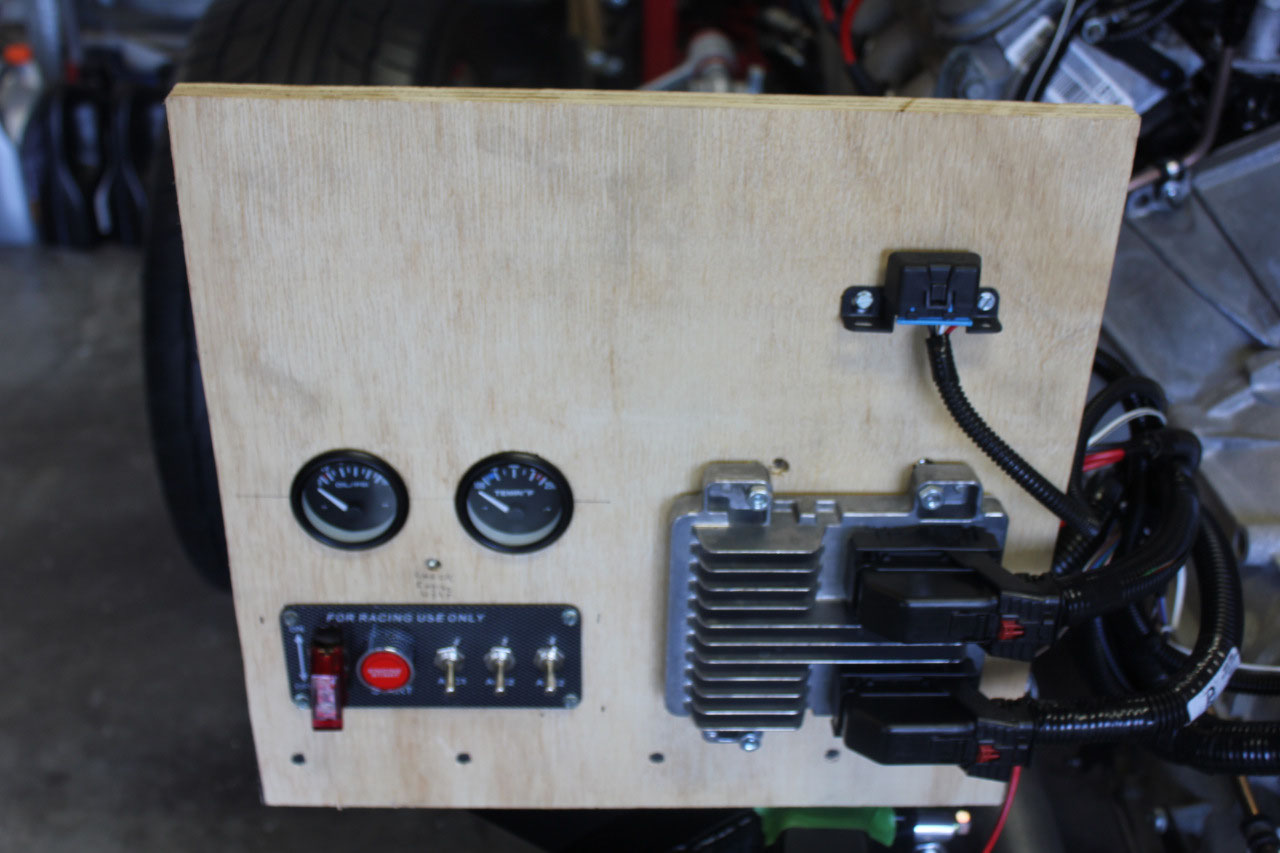
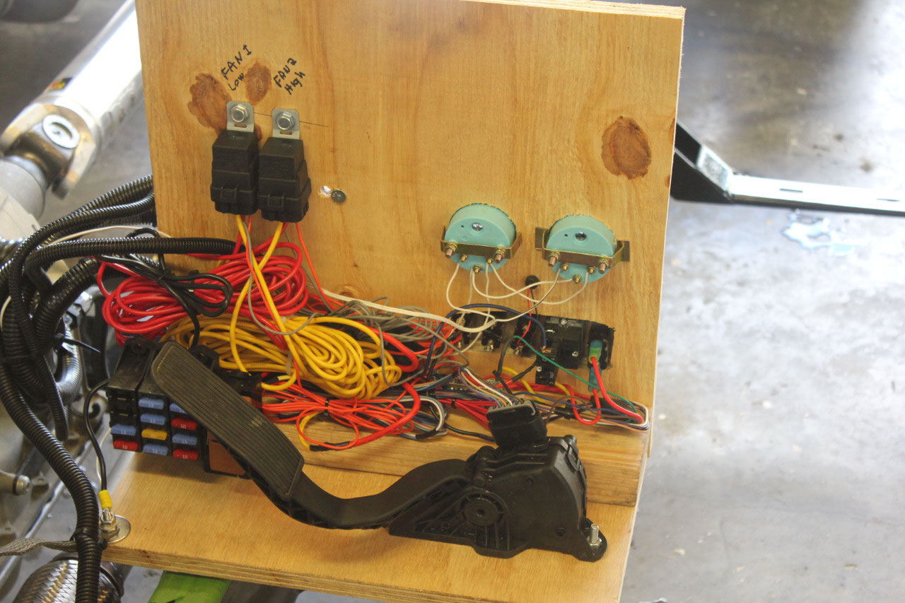
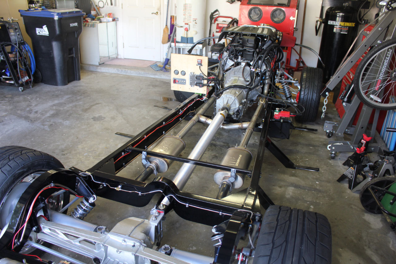
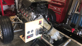
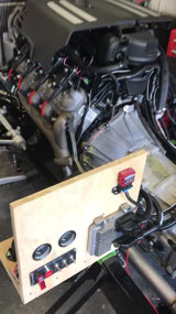
I decided I would just build a plywood panel to mount the computer,
switches, terminal boards, gas pedal and relays. For safety, it also made sense to install an
oil pressure and water temperature gauge.
I used electric gauges as that would also be used in the final assembly,
and wanted to set up the sending unit locations. I ordered a couple of cheap gauges from
Amazon, and figured out what adapters I would need for the sending units. Oil pressure was easy, as I already had a
1/8” NPT hole at the oil cooler blockoff plate above the oil filter. I did need to add a 90 degree adapter to tuck
the sending unit away from the exhaust.
On the rear of the passenger side head, is a 1.5 mm threaded plug that
leads into the water jacket. I just
removed the plug, added a 1.5mm to 1/8” NPT adapter and the water temperature
sensor dropped right in.
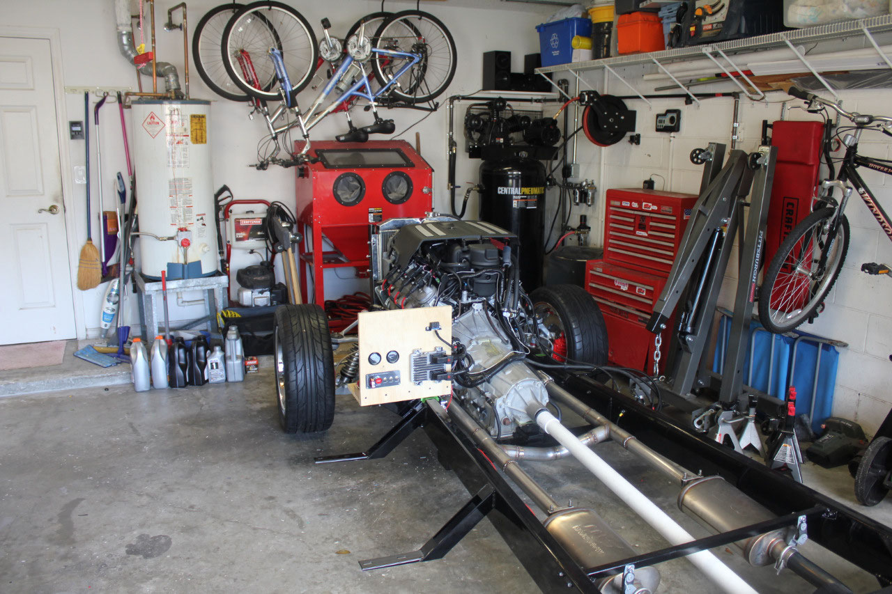
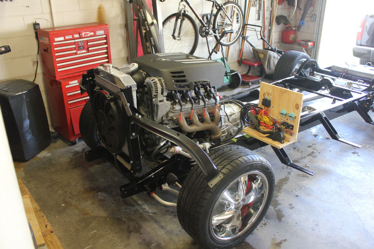
Now that all the fluid reservoirs were complete it was time
to add oil, coolant, power steering fluid, and transmission fluid. All the fluids were added and no leaks! The next step was to lay in the wiring harness
and build the plywood mounting plate. I
was able to locate the mounting plate on the driver’s side body mount and all
the wires would reach.
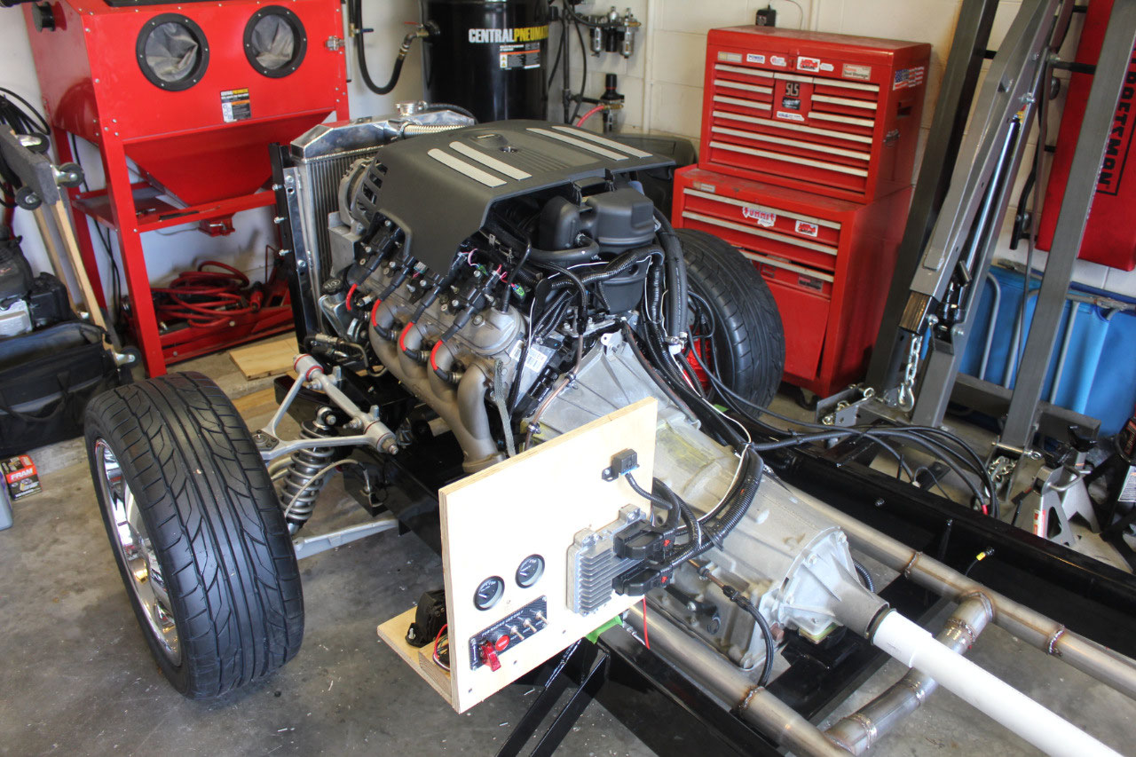
The PSI
Conversions wiring harness dropped right in and all the lengths and connectors
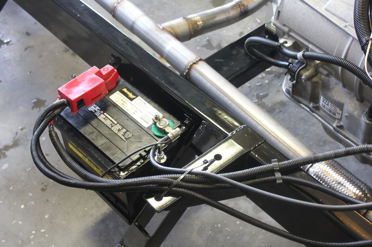
were perfect. I mounted the battery tray
to the frame and was able to reuse the battery cables that came with the
engine. I did have to run a new 4 AWG
wire from the alternator to the battery cable positive terminal. Of course, crimping lugs on 4 AWG wire meant
I had to buy a hydraulic crimper which made quick work of the crimp job. I set up 2 terminal boards, one for +12 VDC
battery power and one for switched +12 VDC.
I also had to run a wire for the start button to the starter solenoid
which for some reason was not included in the harness. I wired up the gauges, and even added a Check
Engine Light to the panel. I wired up
two fan relays and added a connector at the fan pigtail to facilitate maintenance. Of course, I also had to run a fuel pump wire
back to the fuel tank, but this was only temporary, as the real fuel pump wire
will need to be part of the chassis harness.
The wiring all looked pretty good, and it was time to look
for a battery.
Since I was using the
stock frame mount battery box, which was designed for a 6-Volt battery, I was
somewhat limited in battery size to the confines of the battery tray. This meant I needed a 9” x 7" x 8” tall battery. I
also wanted the positive terminal on the left so my battery cable configuration
would work out. Turns out, this is a
Size 85 battery, and while I was originally going to use an expensive Optima
battery, the dimensions seemed a little off, so I ended up with an AutoZone
Duralast Gold 5-year battery which should work just fine.
After hooking up the battery without incident, we were
getting close to the moment of truth. I
put a couple of gallons of fuel into the tank, connected a fuel pressure test
gauge to the fuel rail and hotwired the fuel pump. The fuel pressure read about 60 psi which is
perfect. I connected the OBD diagnostic
to the port and tried to establish communication to either my phone or to my
laptop with no luck. I connected to the
Silverado and it worked fine, so it had to be something with the ECM.
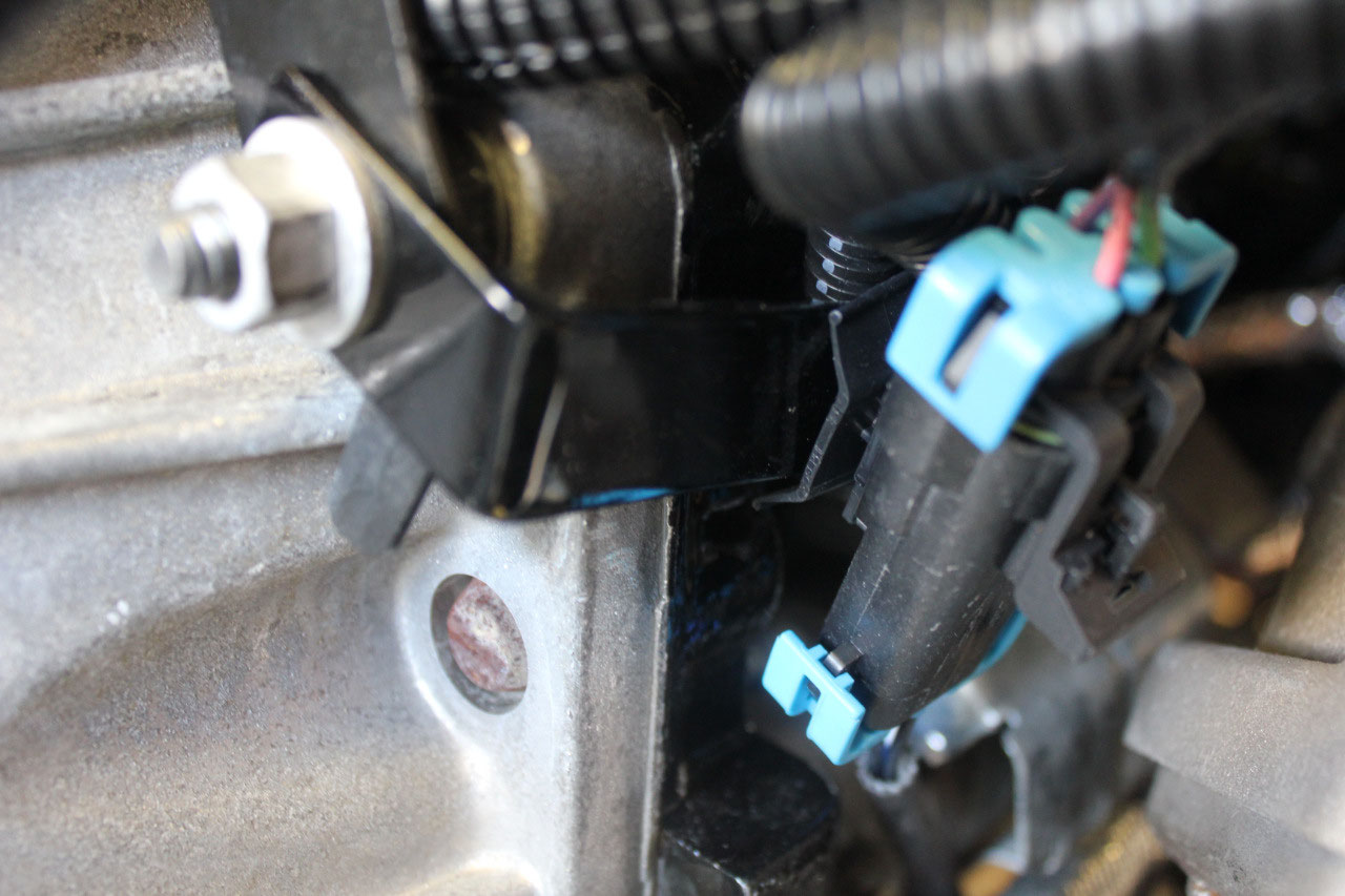
Then I remembered all the warnings about the
transmission connector on the 6L80E. The
PSI Conversion website even had a video showing how to be sure the connector
was mated correctly. Knowing all this, I
had paid close attention to the transmission connector hookup, and was sure I
had done it correctly. Of course I
hadn’t. And when I disconnected it and
looked closer, I realized it was not fully seated just as they had warned. I reseated the connector correctly this time
and the communication problem with the OBD was resolved!
It was now the moment of truth. I flipped the switch to ON and pressed the
START button and the engine fired right up and ran! Oil pressure and the OBD looked good, but I
had to shut it down quickly as the driveshaft was not yet installed and
transmission fluid began pouring out of the tailshaft. Luckily the driveshaft from Denny’s
Driveshaft was due later that same day, and when it came in it fit
perfectly! When I fired it back up, it
all looked great with no leaks anywhere.
I let the engine warm up, hoping to check out the fan relay and see if
the fan would keep the engine cool.
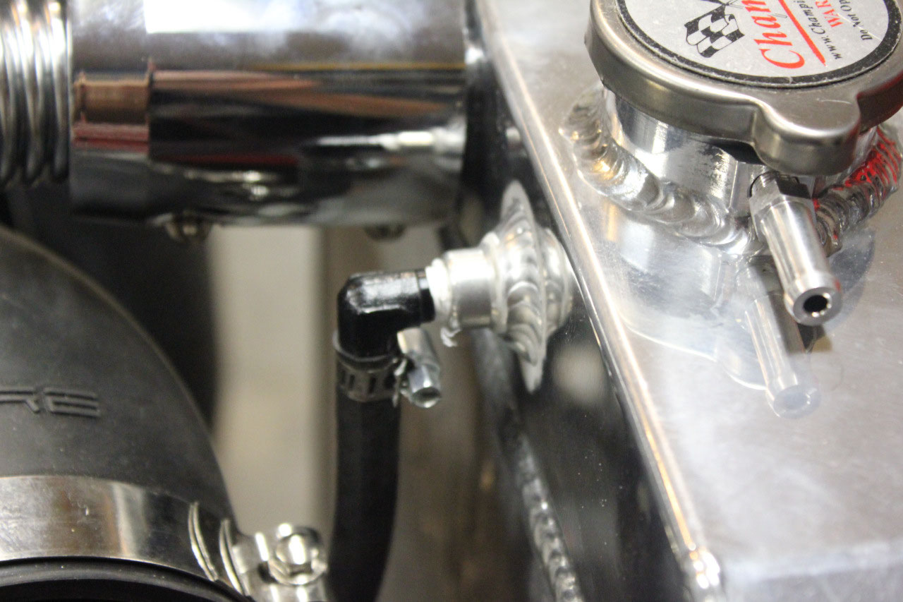
Unfortunately, as soon as the thermostat opened at 190 degrees, the
upper radiator hose blew off the waterpump.
Thinking I had forgot to tighten a clamp, I reconnected the hose, made
sure everything was tight, refilled the coolant and tried again with the same
results. It turned out the reducer that
took the 1-3/4” coupler to a 1-1/4” coupler did not have enough friction. I decided I just didn’t like the design and
ordered a 1-1/2” to 1-1/4” coupler and was able to squeeze the 1-5/8” hose into
the 1-1/2” end and the 1-1/4” end to the waterpump. I tightened everything back up, refilled the
coolant, and tried again. This time
everything worked perfectly and the temperature rose to 190 degrees, opened the
thermostat and the fan came on at 195.
When the fan came on at 195, it cooled the engine to 192 where the fan
went back off again. It all worked
great! Of course, it wasn’t hot enough
to switch on the high speed relay, but I’m sure it will be plenty warm in the
summer to test the Fan-2 relay.
Everything was looking good, when the check engine light came
on. The OBD showed it was a PO-174 code
(Bank2 Lean). Eventually it would also
show a PO-171 (Bank1 Lean) code also. Of
course, this sent me to the internet I search of a solution. It turns out this code or pair of codes is
normally associated with a manifold vacuum leak which is evidently fairly
common with the Chevy 5.3 plastic intake manifold. Before I got too panicked, there were several
suggestions to look for a vacuum leak including the “propane test” where you
point an unlit propane gas bottle at the intake joints while watching short
term fuel correction to look for a jump.
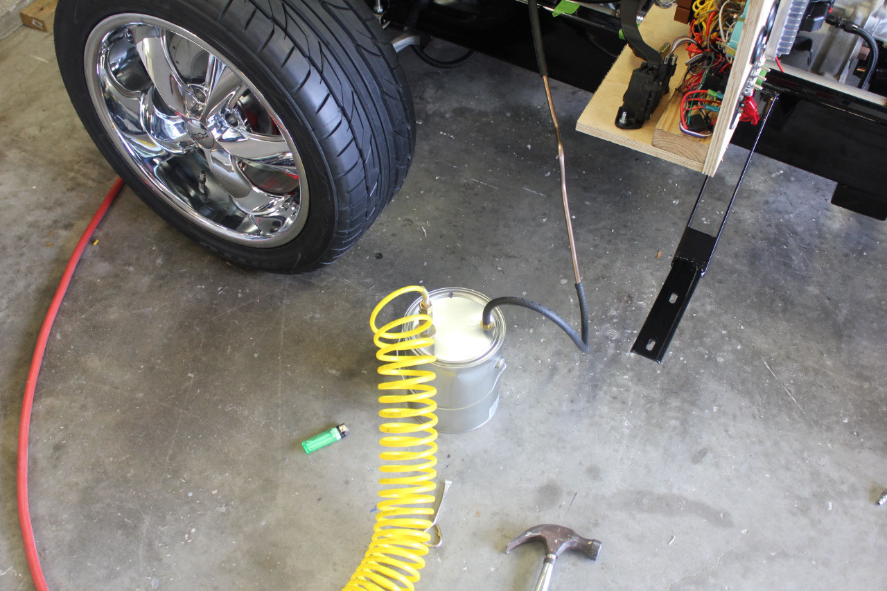
Or building an intake smoke detector, where you use low pressure
compressed air and a paint can to inject smoke into a sealed intake and look
for smoke escaping. I tried both methods
and found no evidence of a leak.
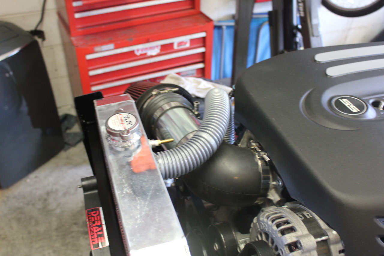
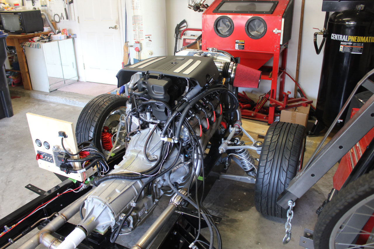
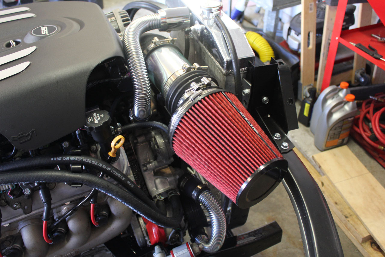
I also found that the Chevy 5.3 does not have a
PCV valve, it just has a PCV orifice which is a calibrated vacuum leak orifice between the inlet air by the
MAF Sensor and the orifice in the driver’s side valve cover.
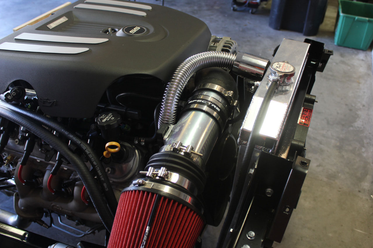
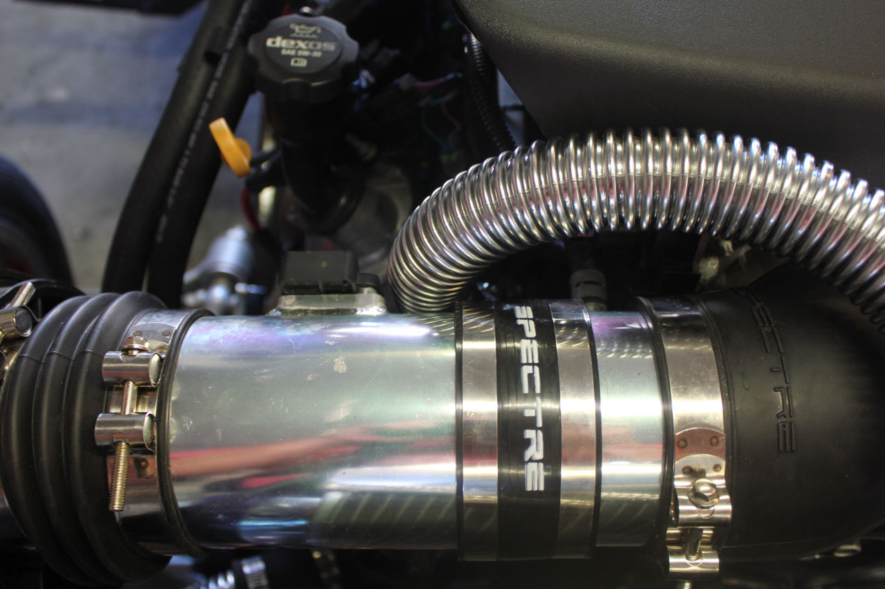
The driver’s side valve cover was not
blocked, but I had moved the inlet side intake to the base of the air filter
before the MAF Sensor instead of between the MAF Sensor and the throttle body
as was the original design. I did this
because the aftermarket cold air inlet was too long and I needed to shorten it
up. I looked at design recommendations
for cold air inlets and decided buy a coupling and add the section of cold air
inlet that contained the PCV port back in between the MAF Sensor and the
throttle body. I hooked everything back
up and the check engine light did not come back on! I checked both the short term and long term
fuel correction and both were hovering around 0 +/- 5 which is excellent.
The last test was to jack up the rear wheels and try the
transmission in both forward and reverse.
Both forward and reverse worked perfectly and it should be ready when I
have a steering column and brakes! I
also wanted to test out the steering rack, so I bought the u-joint down at the
rack and a length of steering shaft.
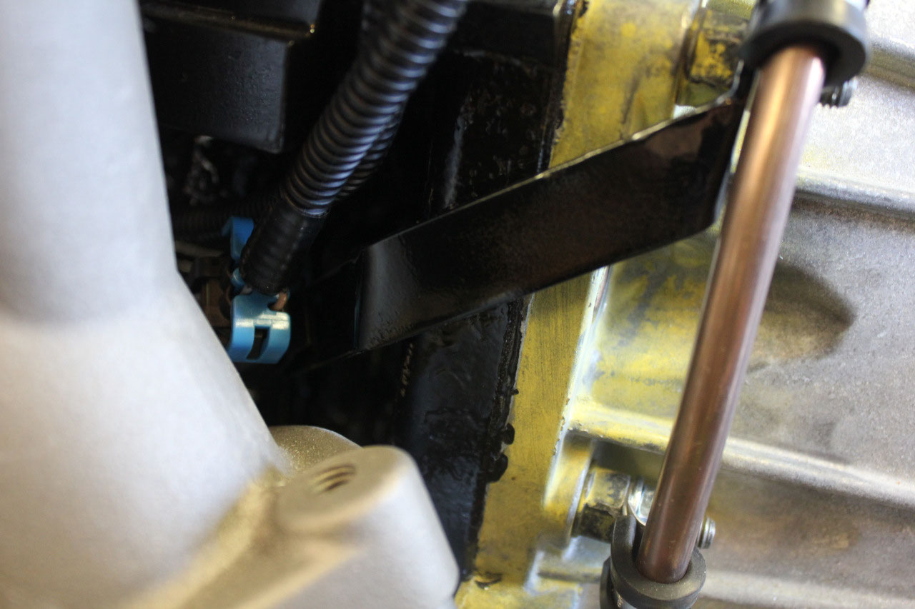
That’s when I found out I have a clearance problem between the u-joint
and the driver’s side motor mount. It
almost fits, but it looks like I will need to trim some of the metal away from
the mount. The mount is a 4-sided piece
of steel that Darryl at Rockabilly put together. I will need to clearance some of it at the
bottom, but I believe it is way overdesigned and the removal of some of the
metal should not have an adverse effect.
At this time, I’m not sure just how much metal and where it needs to be
removed and I won’t know for sure until I have a steering column installed in
the cab. So for now, I was able to
rotate the shaft and prove the power steering rack works correctly, and I will
leave the motor mount modification until after the steering column is
installed.
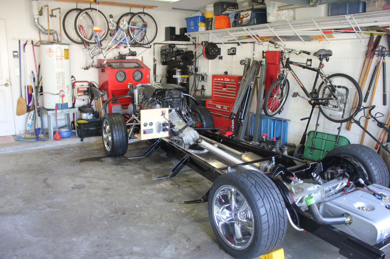
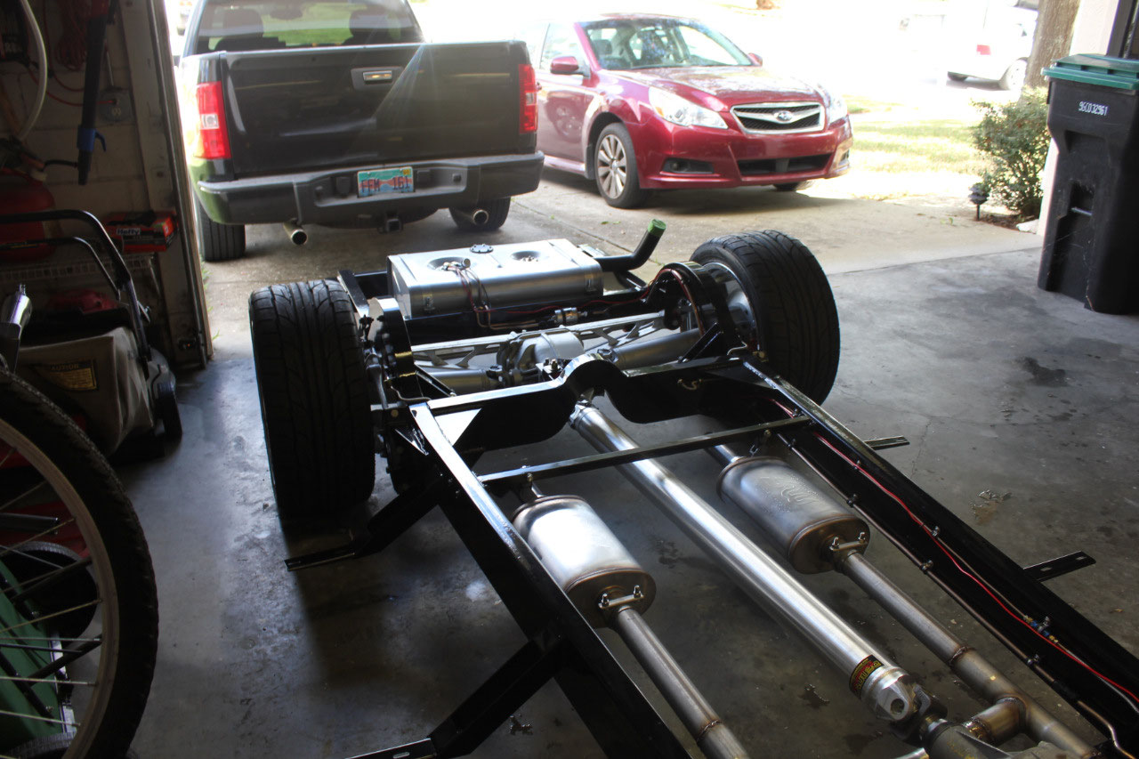
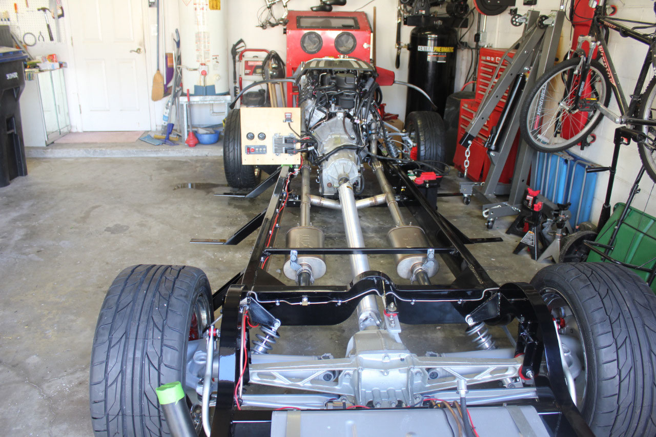
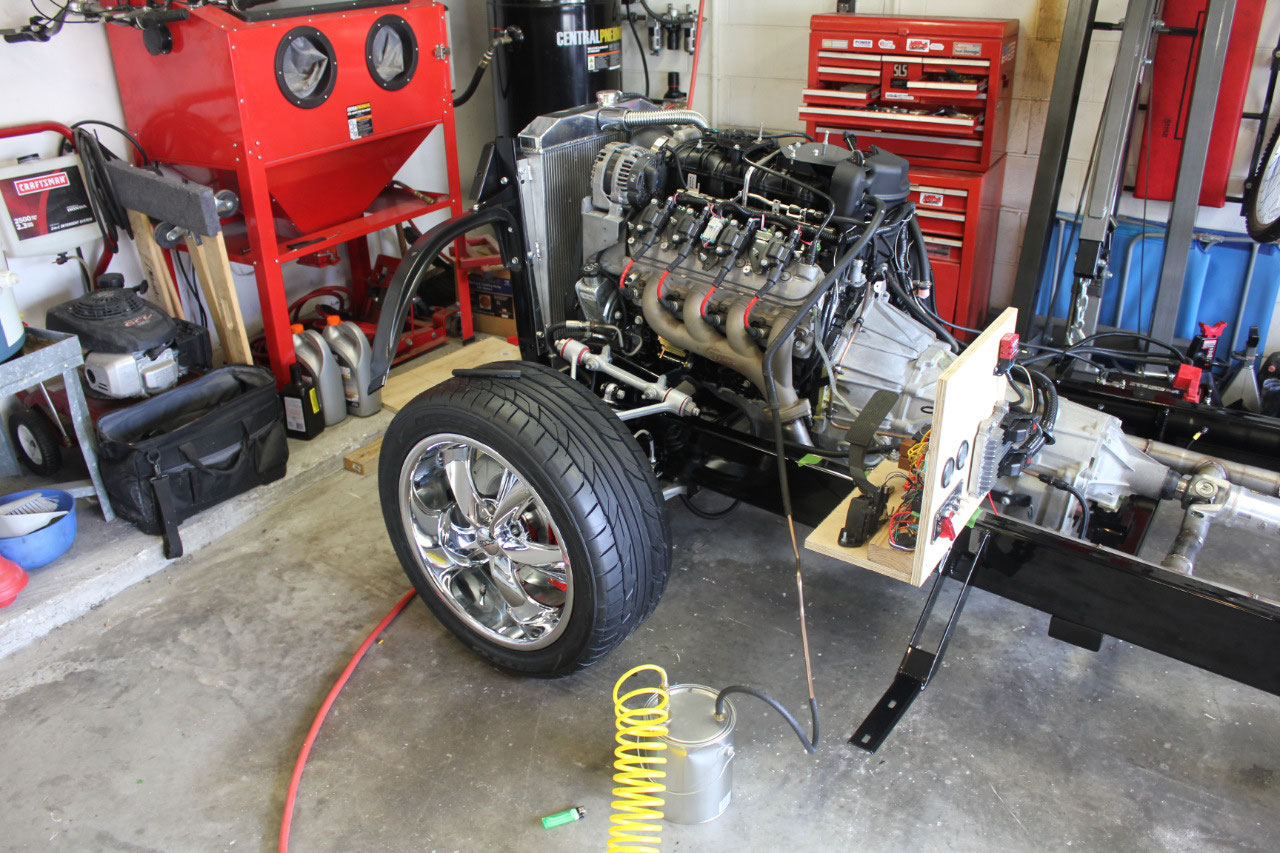
At this point, the chassis is generally complete. I start the engine about once a week to make
sure it still starts, and sometimes let it warm up to operating
temperature. For Christmas, I got a set
of wheel dollies so I can now move the chassis around the garage easily. After January 1, I will begin the search in
earnest for a body so I can begin the next stage of assembly. I can hardly wait!

2025-05-22