 Orlando, Florida, United States
I am finally getting caught up with entries in this
blog. For the past several weeks, I have
been accomplishing a lot on the truck, but have been neglecting to blog about
the progress. Fortunately, I have been
taking pictures all along, now I just need to remember what each picture is
about. The coronavirus still has us
stuck at home. Our March cruise and our
trip to Spain & Portugal in June have been cancelled. Working on the truck is a great cure for
cabin fever!
At this point, most of the cab and interior are done, with
the notable exception of the glass. For
now, I am leaving the glass out, as I am still not sure when and how much I
will need to disassemble for paint. At
this point, I needed to decide whether the next step would be the doors or the
front sheet metal. Either would be fine,
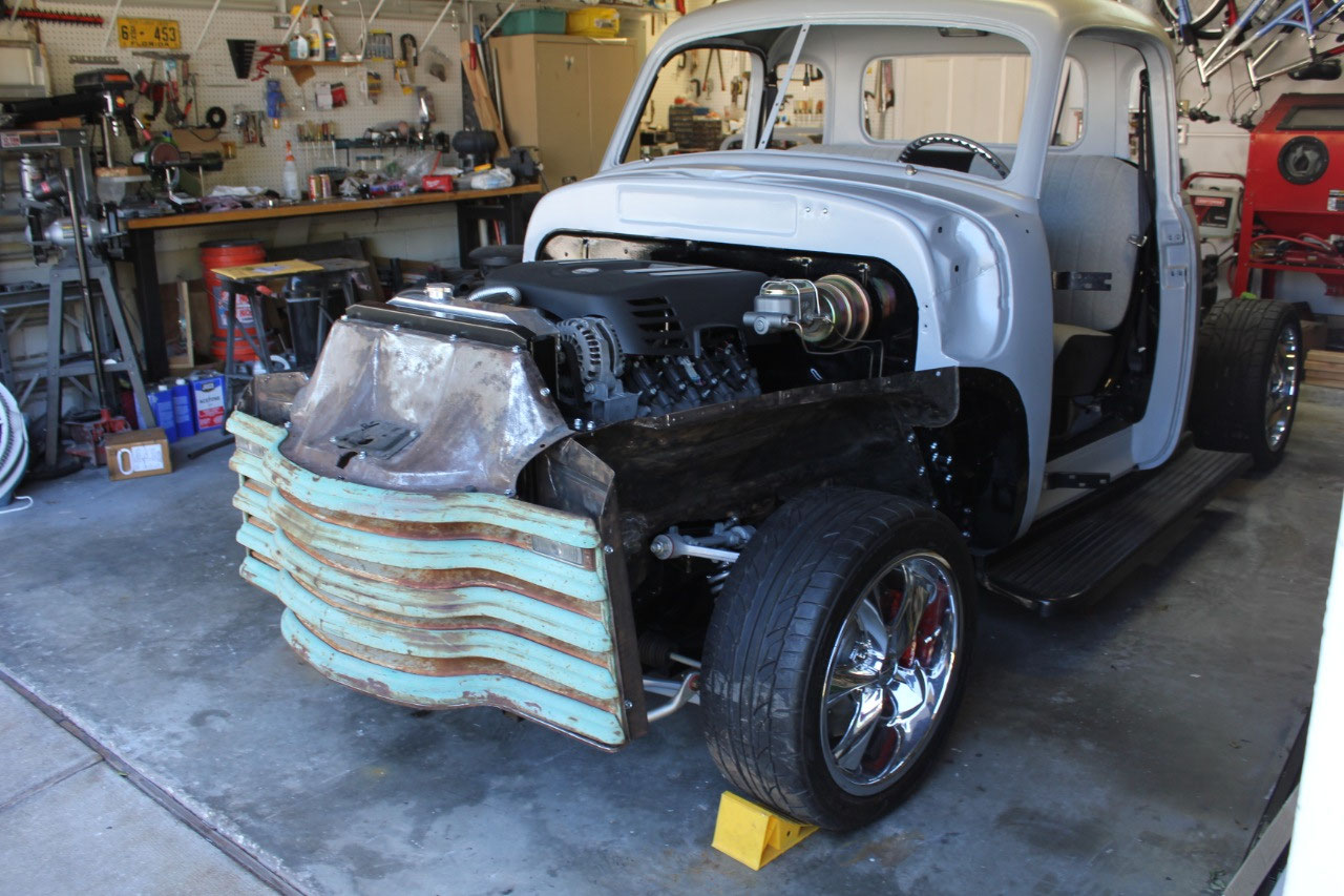
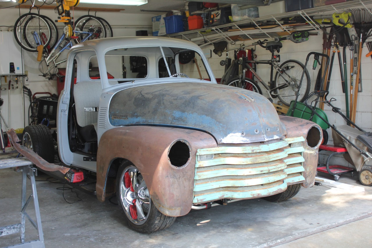
but in the end, I decided that I was tired of looking at the fenders on the
floor, and the hood on the back porch, and that installing the front sheet
metal would give me more space in the garage, and make the truck look more like
a truck.
But before I start on the actual sheet metal, I have a
couple of leftover problems to solve.
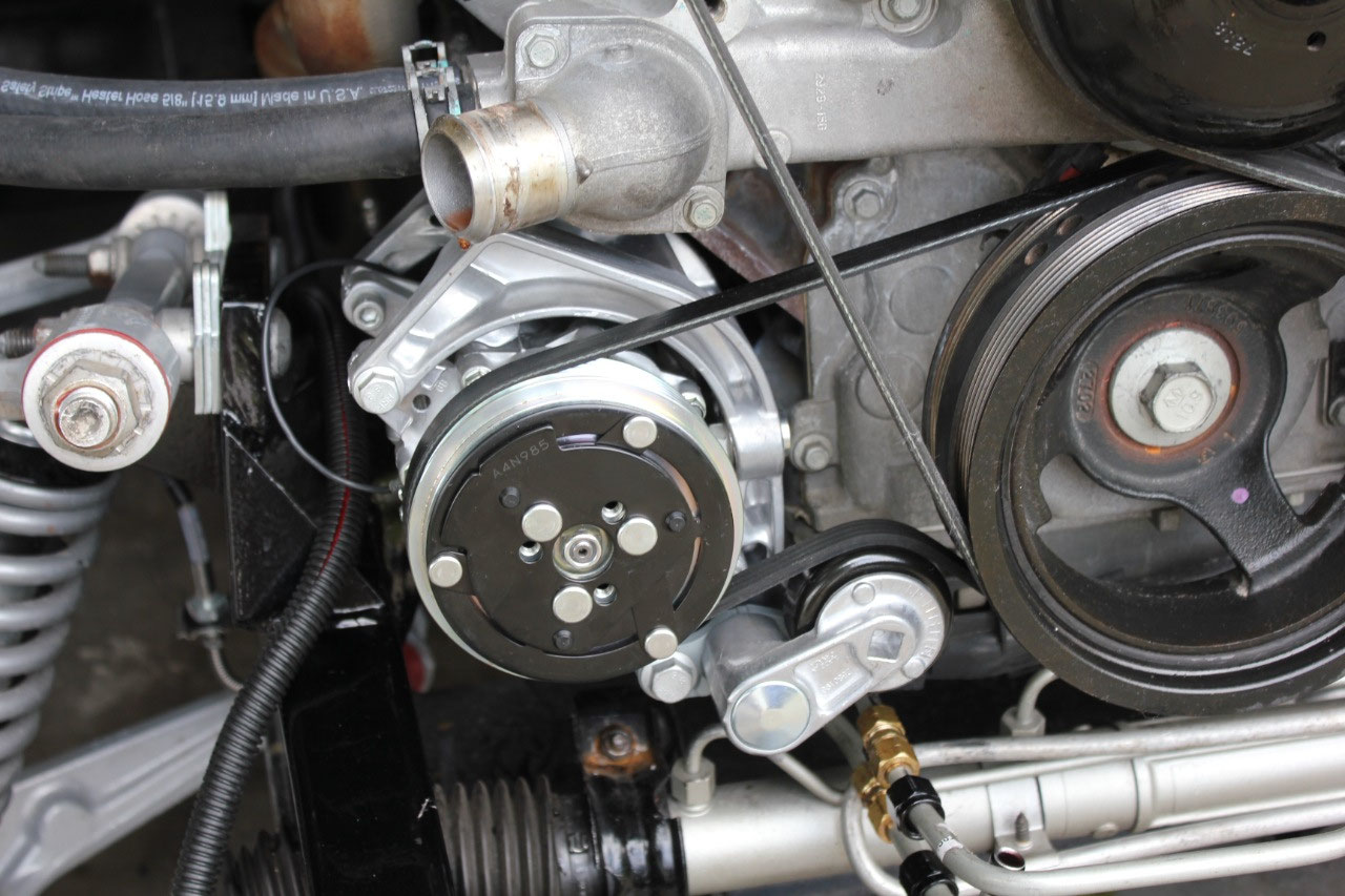
First, I had intended to reuse the original A/C compressor that came
with the engine, but quickly realized that it wouldn’t really work. So I found a bracket from Holley (P/N 20-159)
that looked like it would work to mount a Vintage Air Sanden SD7 compressor in
that location. Before ordering the
compressor itself, I ordered the bracket to see if it looked like it would
work. I removed the old A/C compressor
and installed the Holley bracket, and it looked like it would fit great. Actually, there was a little more room than
the factory compressor.
While waiting for the compressor to arrive, I decided to
tackle the problem of the front sway bar.
In the original front sheet metal fit, I found that the wheels that I
had selected (18x8 – 1mm offset) to clear the sway bar were too wide and
interfered with the front fender lip.
The replacement wheels (18x8.5 – 34mm offset) would clear the fender
lip, but hit on the sway bar.
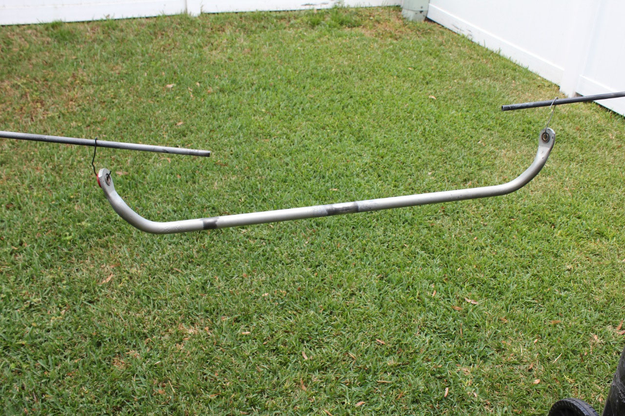
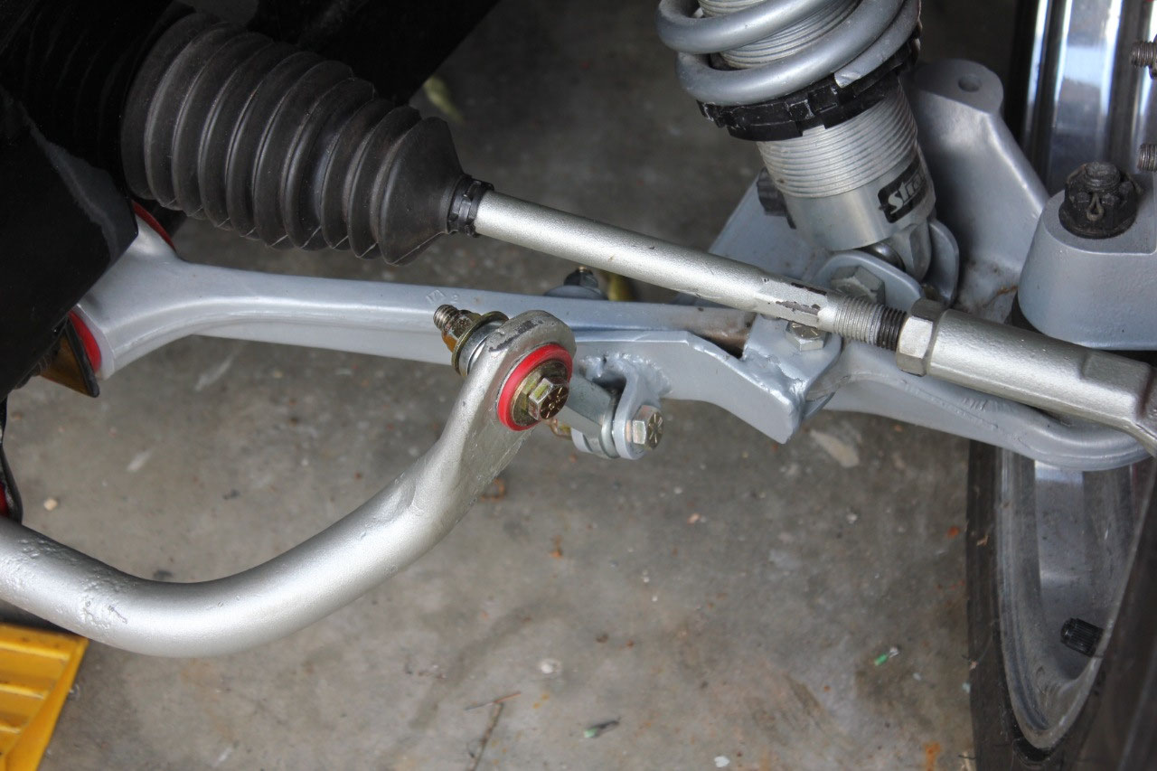
I searched
everywhere for a narrower sway bar, but in the end, I decided I would just try
to cut and weld it in the middle and see if it would work. There are plenty of stories on the internet,
both pro and con, but it was worth a try.
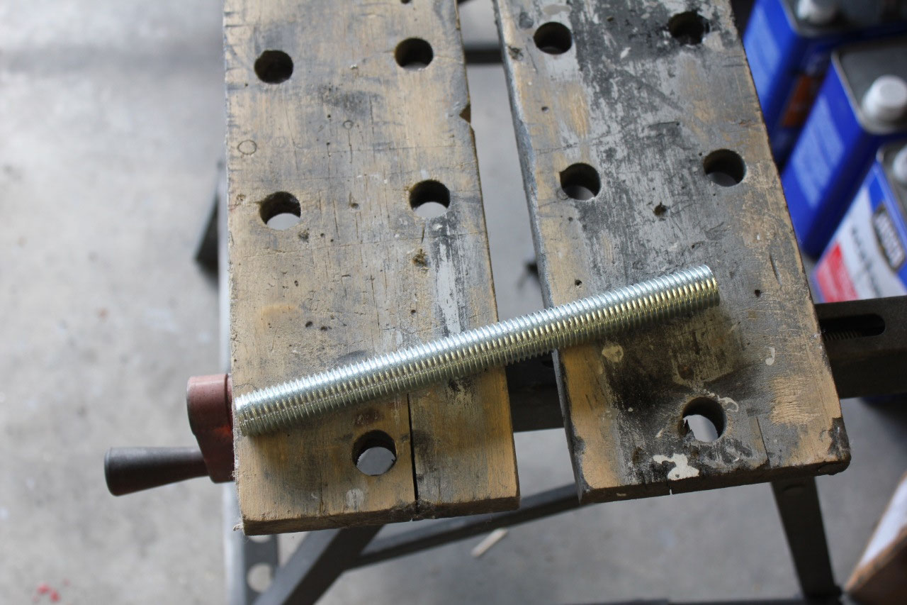
The sway bar is the original Corvette C4 26mm OD bar. It is hollow, with the ID about ¾ inch. I cut about 2 inches out of the center, found
a piece of ¾ threaded rod that would fit in the center with a little grinding,
and slid the 2 pieces together. I
tapered the edges at the cut to give the weld a better place to attach and left
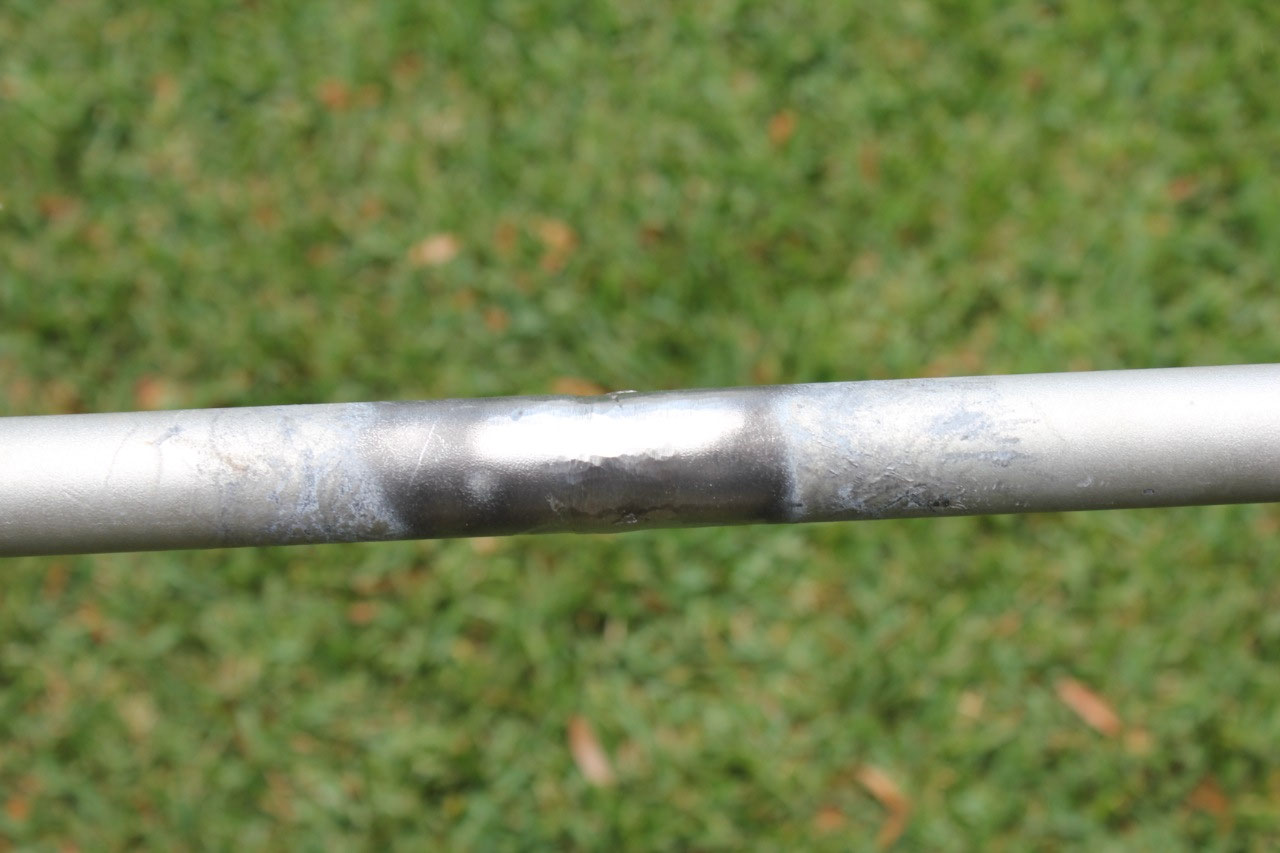
a ¼ inch gap so the weld could attach to the threaded rod. I welded everything up and then ground the
outside smooth. It looks really good
from the outside, and after a little paint touchup you couldn’t tell it had
been cut. We’ll see if it holds up!
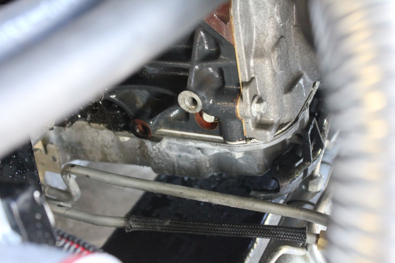
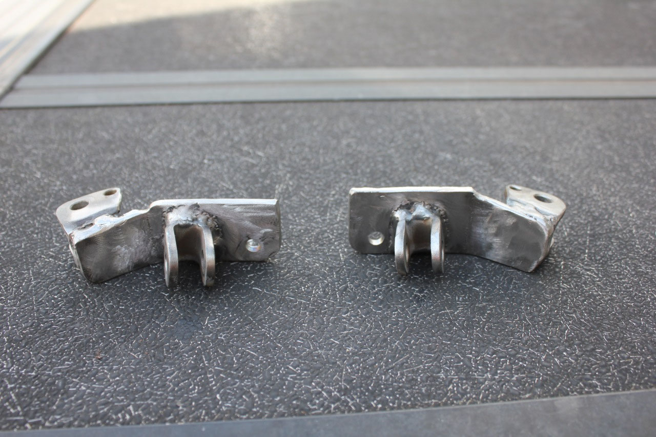
I took the original a-frame attachment brackets that Darrel
had designed, and cut them apart. Using
some leftover 3/16 steel from the steering shaft support, I bent up a bracket
to fit the front of the a-frame.
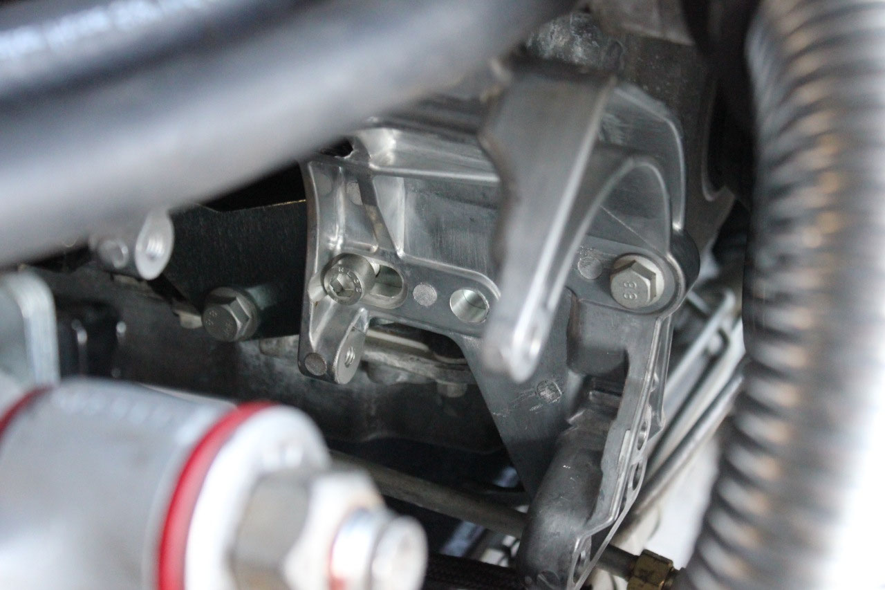
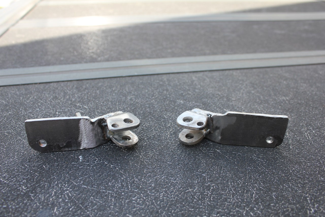
I then
welded the original attachment point to my new bracket and it looks great! A little silver powder coat, and they blend
right in and hook right up. I’m glad I
waited to fabricate these brackets, and I don’t think I would have had the
skill or the confidence to tackle this problem a year ago.
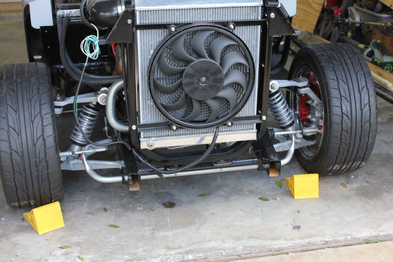
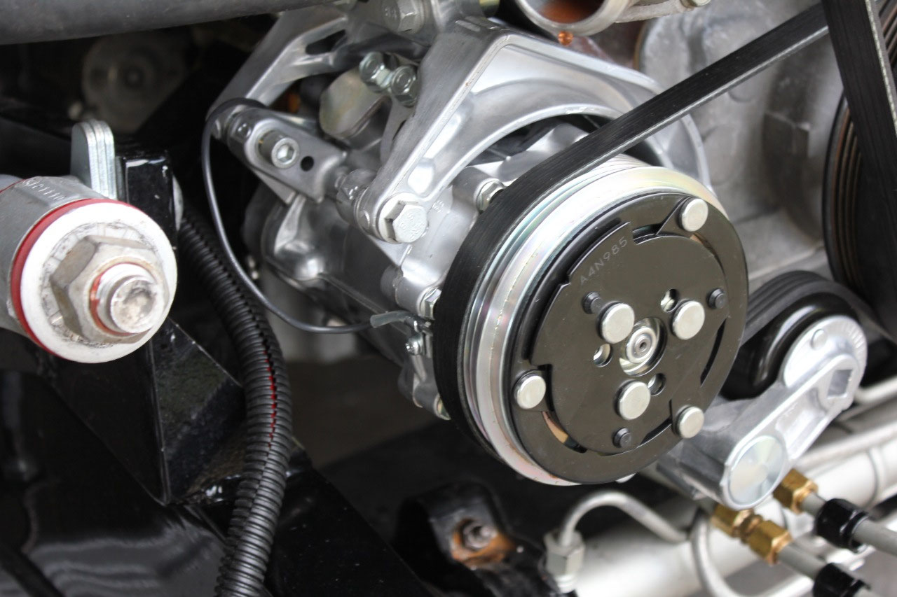
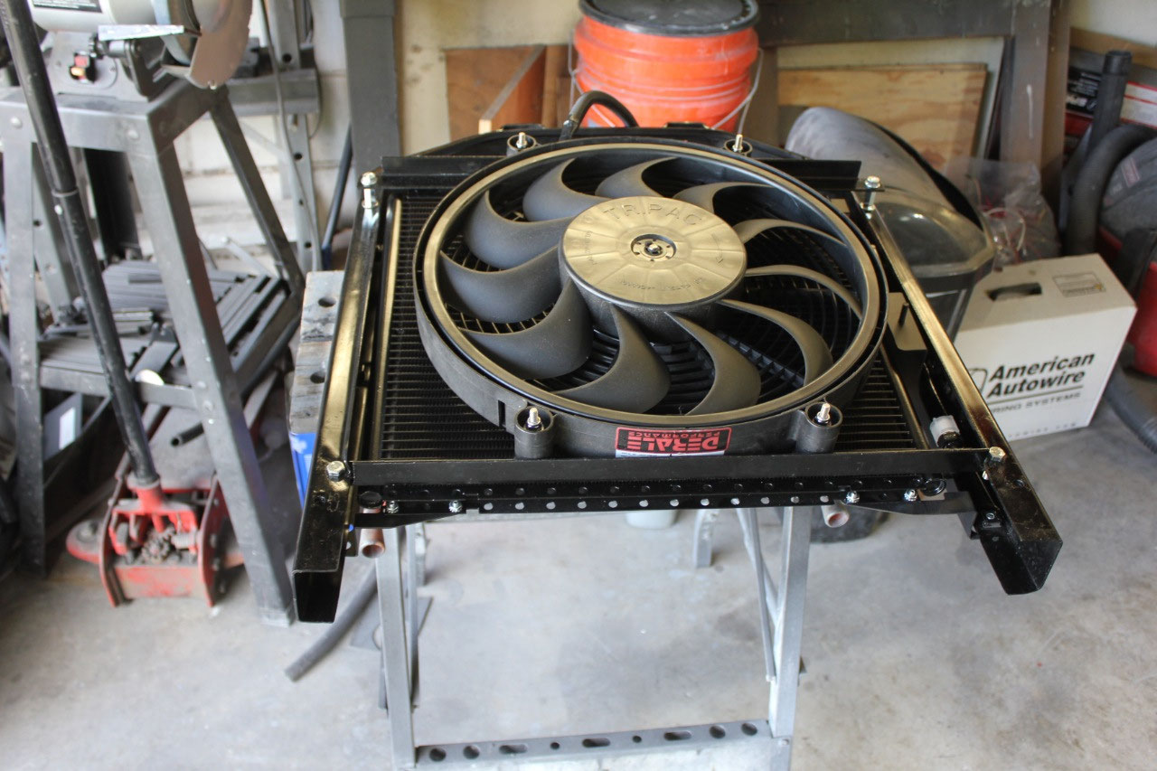
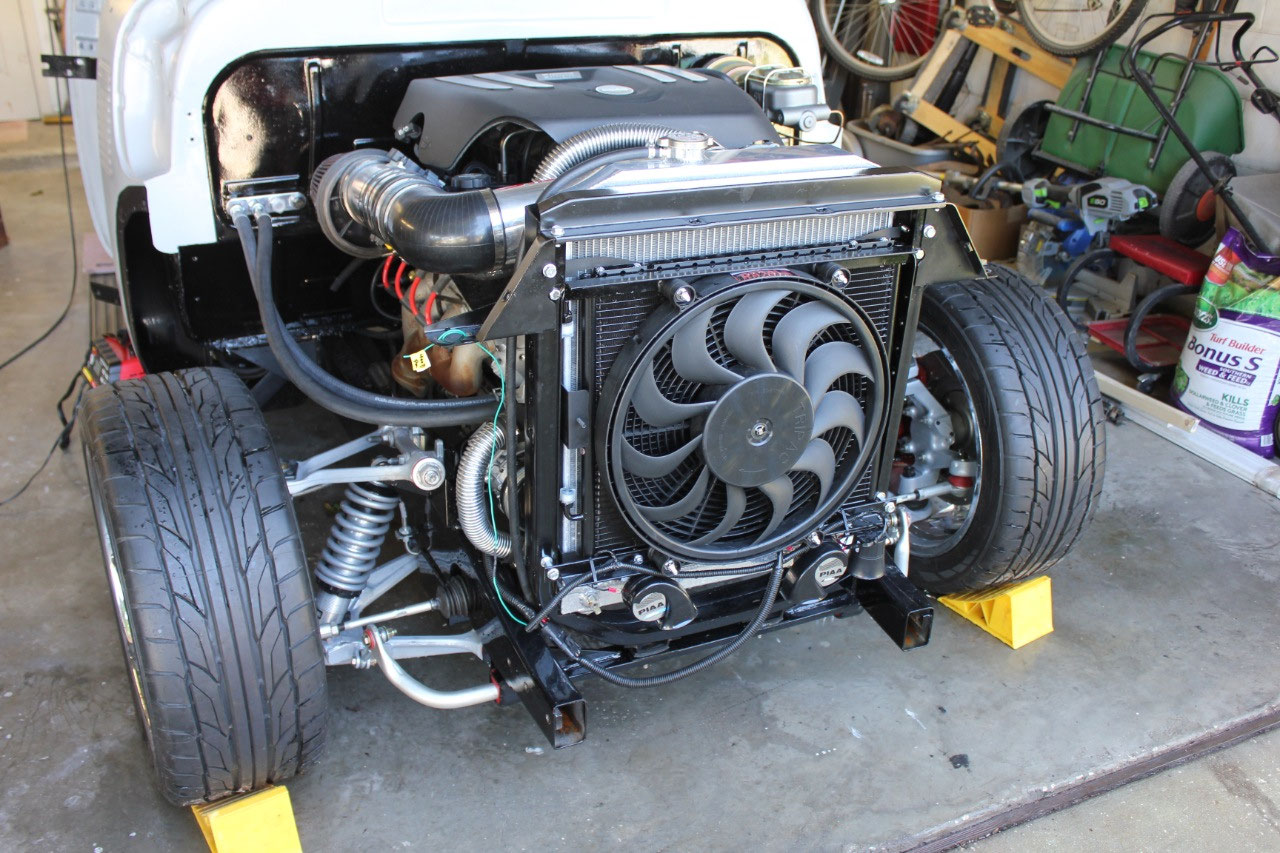
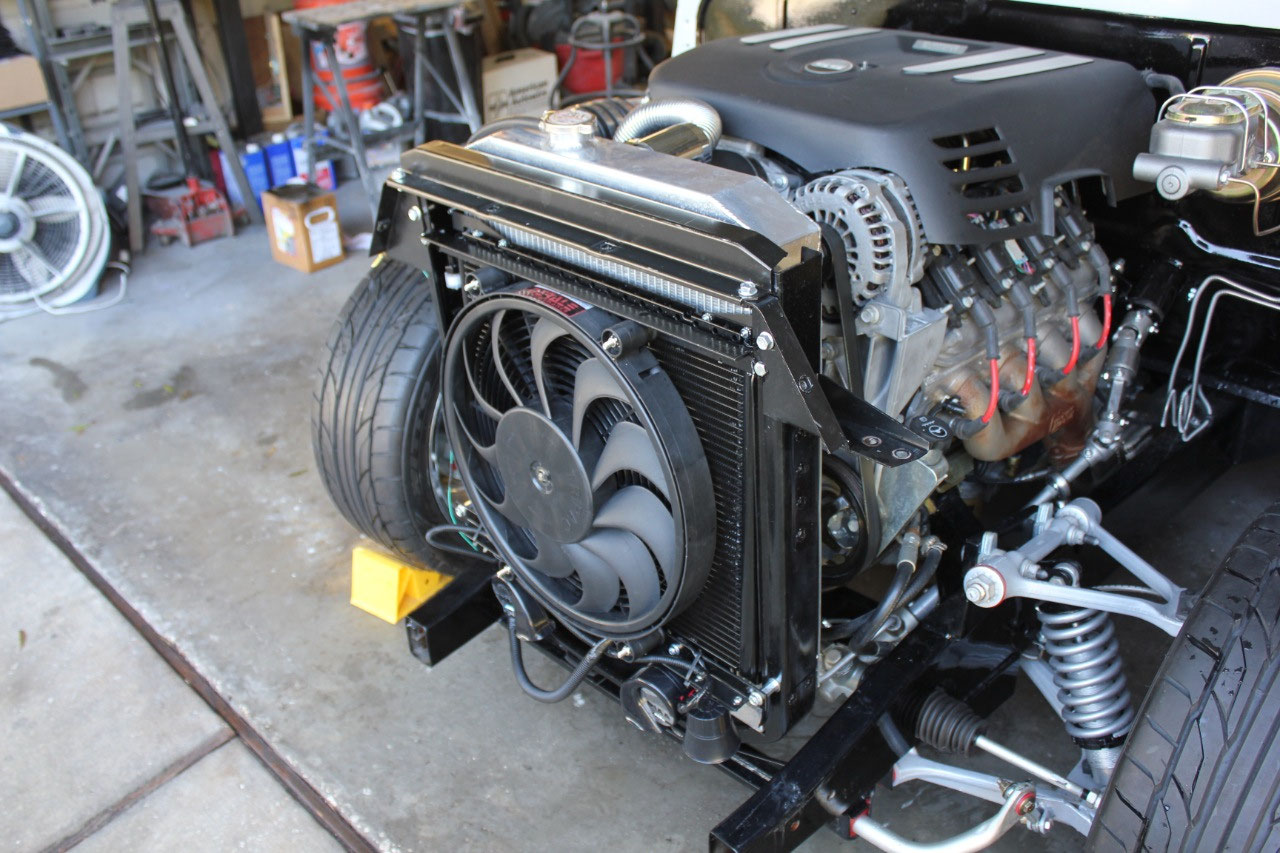
By now the compressor had arrived, and it dropped right in
with plenty of clearance. It was now
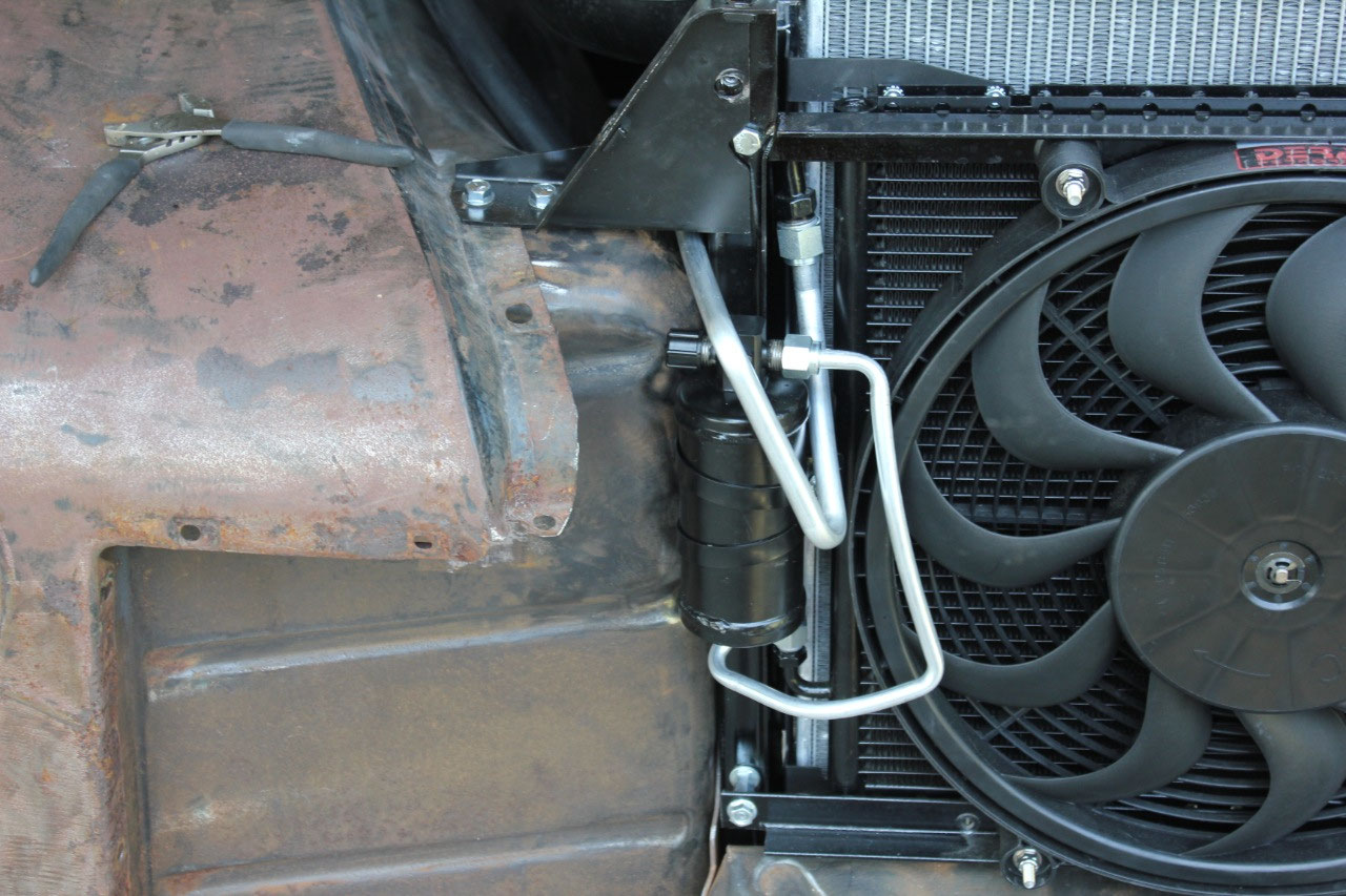
time to tackle the remaining major task of installing the A/C condenser. This was another fabrication task where I
wasn’t sure what to do, but ended up ordering the Vintage Air setup for this
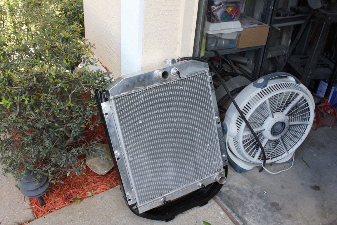
truck and decided I would just need to figure it out. Installing the condenser is easy enough, I
just wasn’t sure what to do with the pusher fan as the Vintage Air setup
assumes a puller fan on the other side of the radiator. They even have a forward mount to move the
radiator and condenser forward to give a little more clearance, but this kit
just wouldn’t give enough clearance to fit.
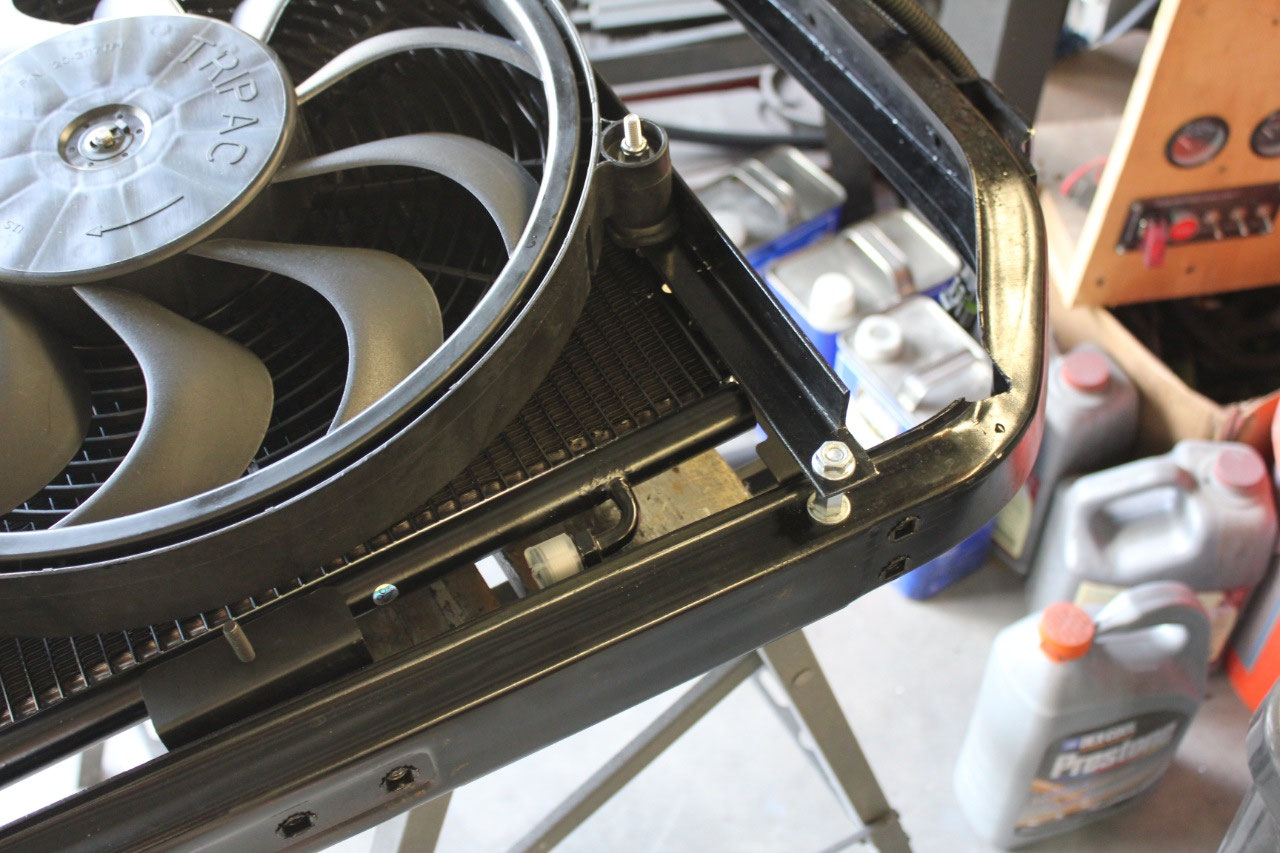
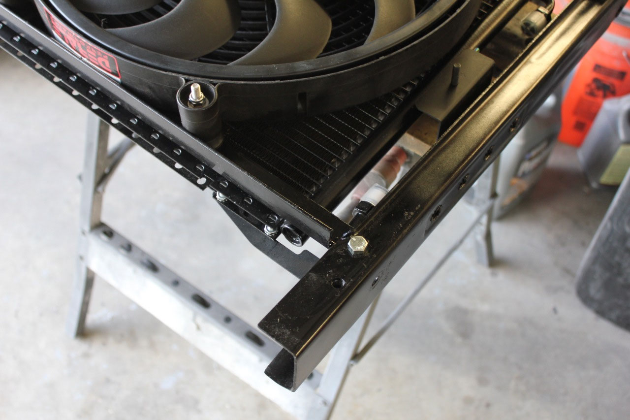
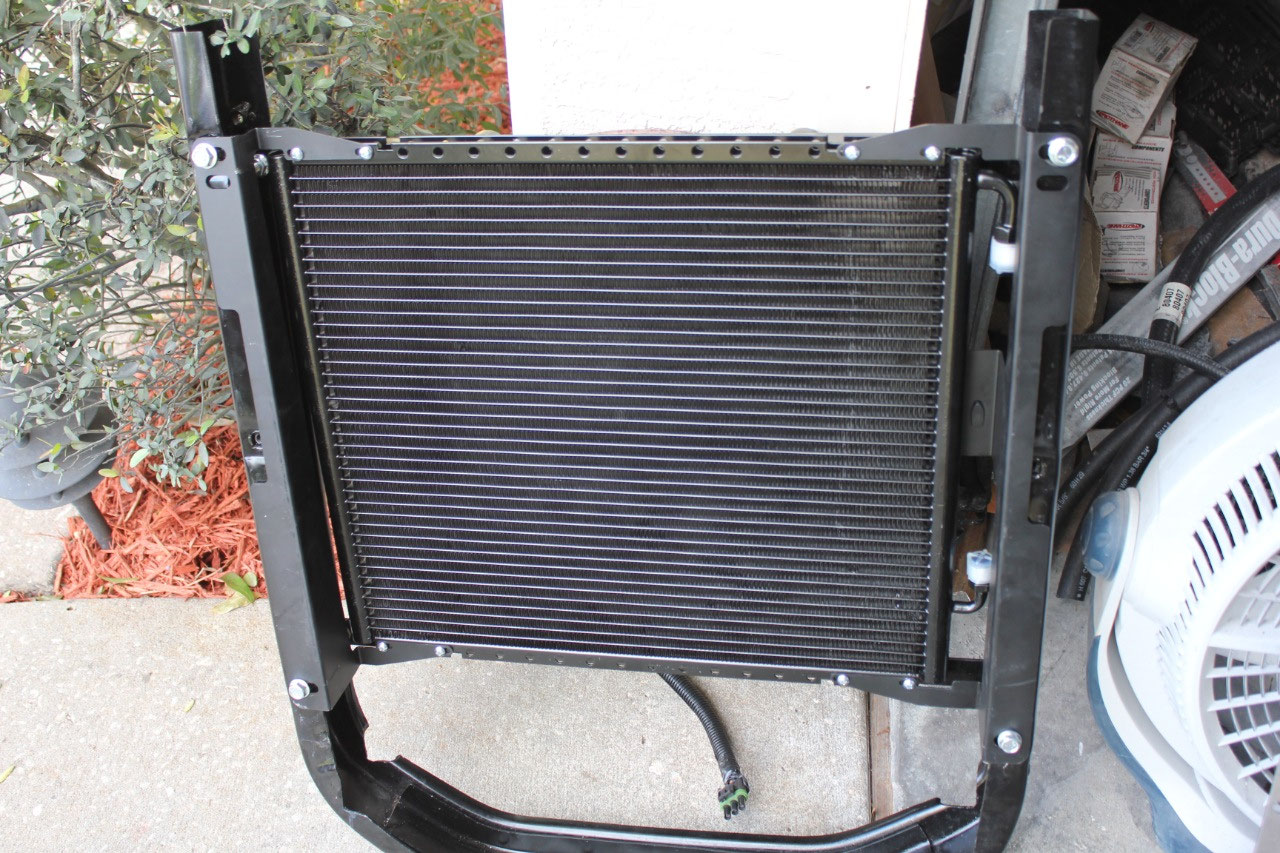
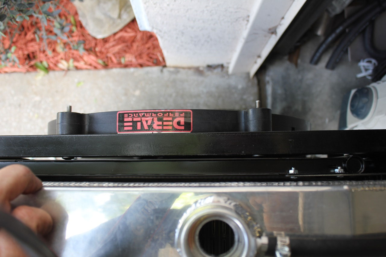
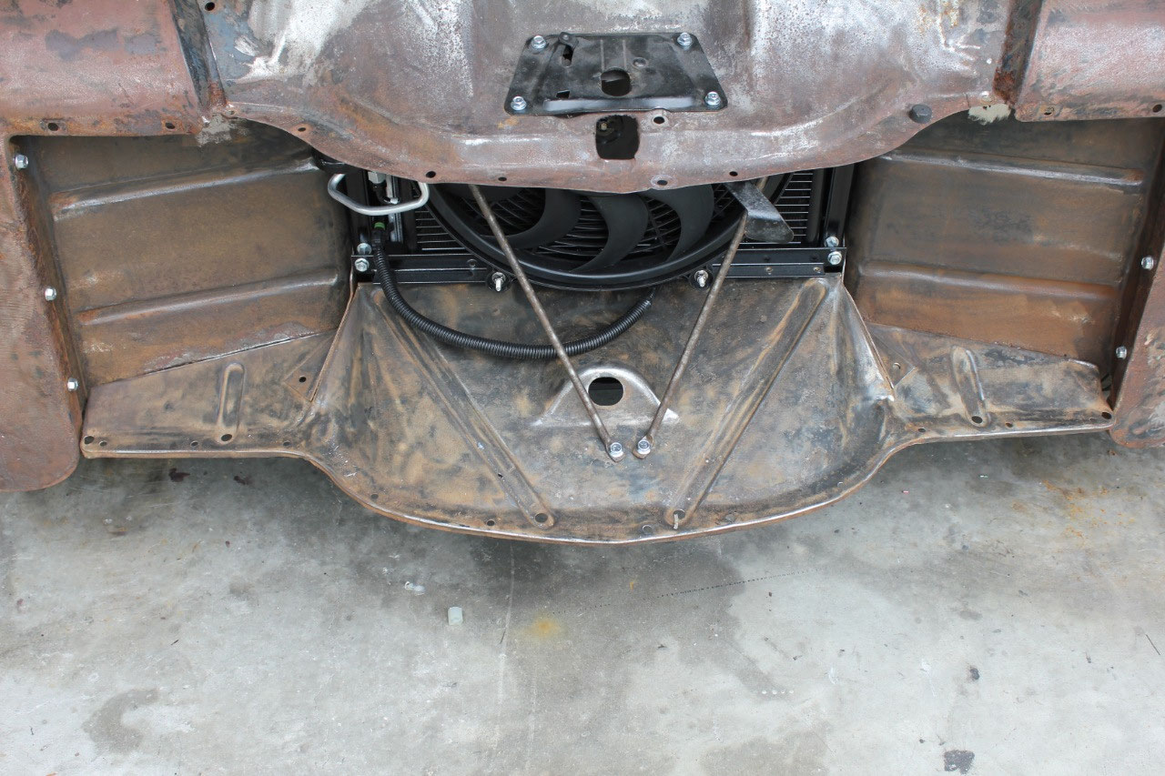
It turns out I was able to fit the condenser, and with some
minor modifications to the angle iron bars I had used to mount the pusher fan,
I was able to move the fan about ¾ inch forward with just enough clearance
between the condenser and the radiator and the condenser and the fan.
The only part I would need to move is the
dryer and it would interfere with the fan.
This sounds easy, but it also meant that the A/C hard lines that came
with the kit would not work either. I
decided to wait until I had installed the remaining sheet metal to see where I
could install the dryer.
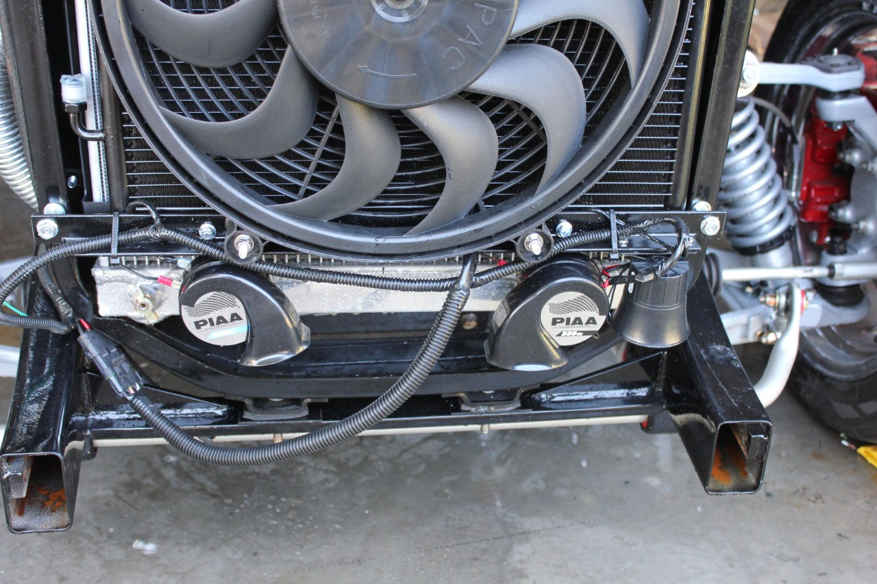
While everything was still open, I decided to go ahead and
mount the alarm siren and the horns to the fan mount bracket and go ahead and
wire it up. There were 2 wires to pick
from up near the front, and as I remembered, one was the siren, and one was the
horn. So I mounted the horns and the
siren, determined that the white wire was the siren, and hooked them up. The siren worked fine and either chirped or
alarmed when appropriate. But I couldn’t
get the horns to work. I played around
with the horn wiring in the steering column and found that the horn button was
not operating the horn relay. The hot
wire was hood but there was no ground.
It turns out that my paint job was so good, that it insulated the column
at the drop, and the rubber vibration isolator in the steering u-joint
insulated the shaft.
When I ran a
separate ground, I could hear the relay click, but still no horn.
Suddenly, it donned on me that there was a set screw at the
base of the steering drop to prevent the column from slipping in the drop. Additionally, when I tightened the set screw,
it cut through the paint and grounded the column perfectly. I traced back through the horn circuitry in
the harness documentation when I realized that the horn wire was in the front
headlight harness that I had not yet installed, and that the green wire that I
thought was the horn wire was actually the hood switch for the alarm system. No wonder it didn’t work! So much for my electrical genius! I guess the horn wiring will come later. Now
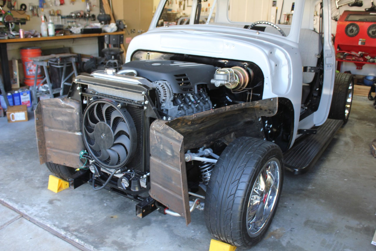
I will tackle the front end sheet metal.
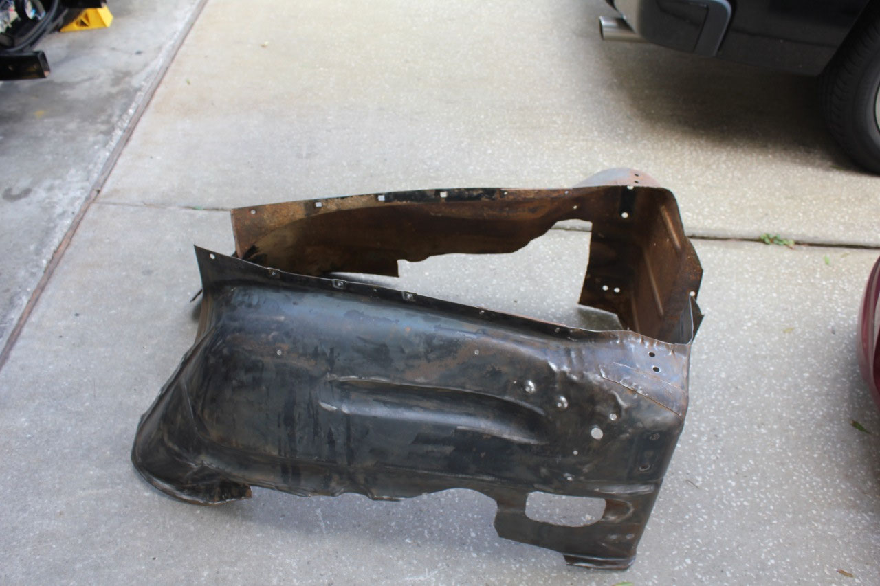
Most of the front end sheet metal had been fit before, to
get a feel for clearances and the like.
The inner fenders had been cut out around the front suspension and
engine interferences, but now was the time to get each of the parts ready for
paint. The inner fenders were really a
mess, dirty, rusty, and I wasn’t really sure they would be usable.
New ones are about $350-$400, but I was concerned
that replacing them would cause fitment issues as most of the replacement sheet
metal doesn’t fit as well as the original.
In the end, I decided to reuse as much of the front end parts as
possible and take the time to refurbish the originals. The plan is to do as much metalwork as
possible, send the parts out for media blast, and bring them back here for
epoxy primer and black paint where appropriate.
The media blaster, Blast Off, that I used for the cab is out of
business, so I will need to find somewhere else when I am ready.
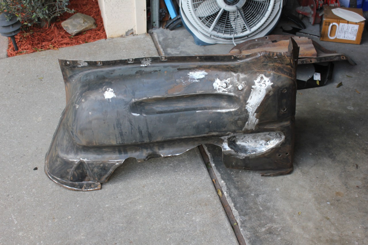
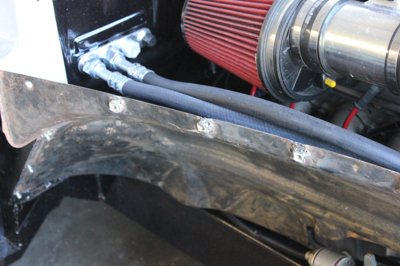
I started with the driver’s inner fender, wire brushed off
the loose rust and remaining dirt and undercoat. It actually did not look bad. There was some pitting, but no signs of rust
through. I removed all the wire harness
clips, welded up all the holes except the mounting holes, and ran a tap through
all the weld in nuts. There was one
clearance hole for the power steering hoses that was cut in during initial
fit.
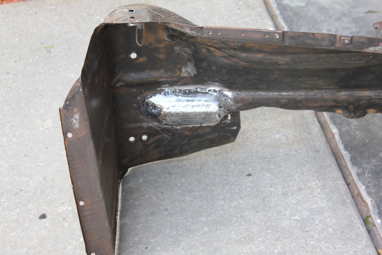
I fabricated a curved plate to
cover the hole and welded it in place.
The inner fender was formed around the original steering box for
clearance, but since I was using rack and pinion, I had no need for the
clearance. In looking at the passenger
side, it was easy enough to bend the driver’s side to look like the passenger’s
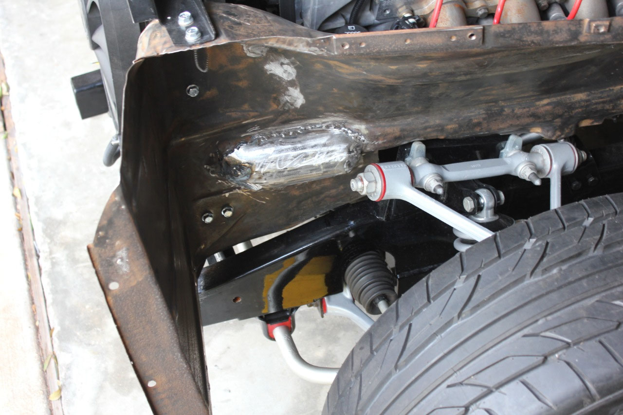
side in that area. Finally, one of the
u-joints on my steering shaft was very close to the inner fender, so I cut a
radius around the u-joint interference.
It all looked pretty good and mounted up easily.
Next, I tackled the passenger’s side. This was actually easier, as I just cleaned
it up the same with the wire brush, welded up all the unused holes, but I also
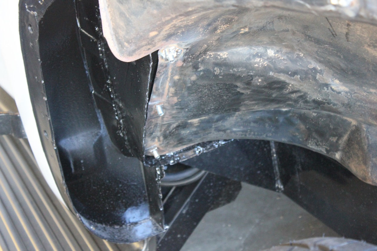
had to replace a few of the weld in nuts as they were missing. There is a large clearance area around the
lower radiator hose that was cut in earlier that I just left open. I don’t really want to close it up as I will
need the opening for maintenance, but I’m nervous about having an exposed
radiator hoes in the wheel well.
I need
to think about a solution, maybe a removable sheet rubber cover, but for now I
will just leave it open. The passenger’s
side inner fender fit fine.
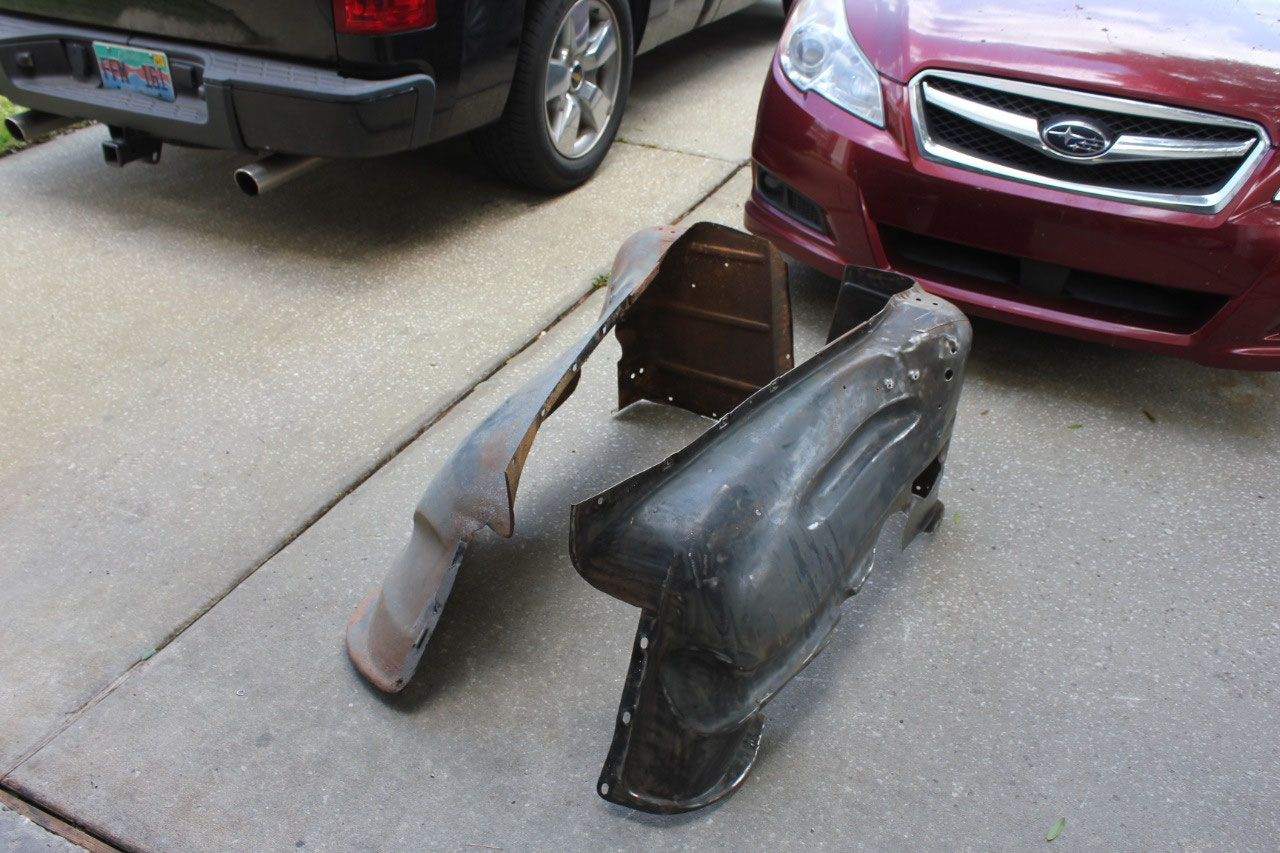
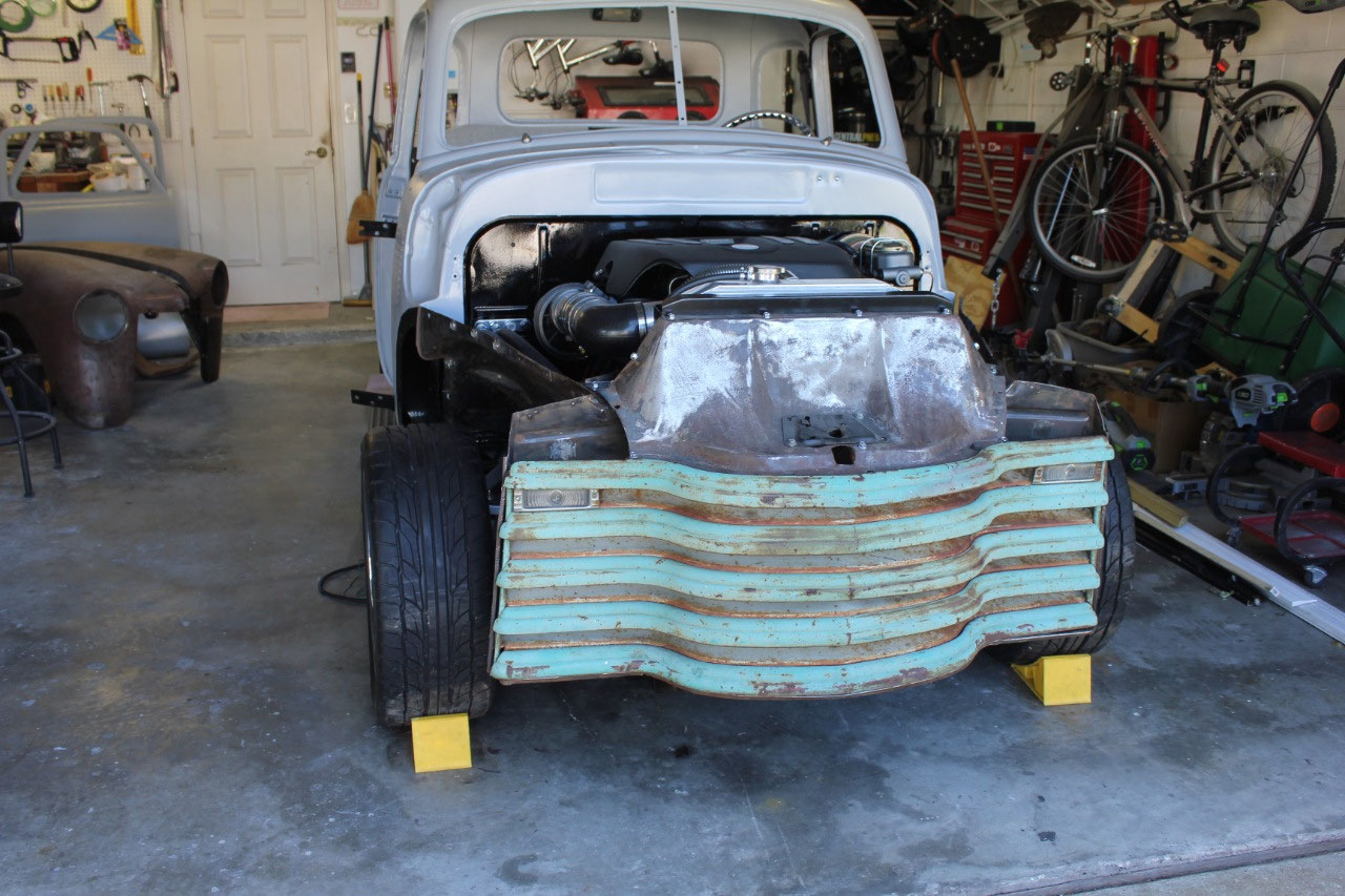
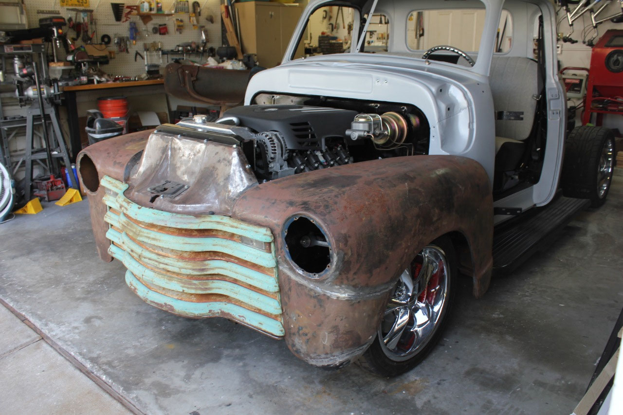
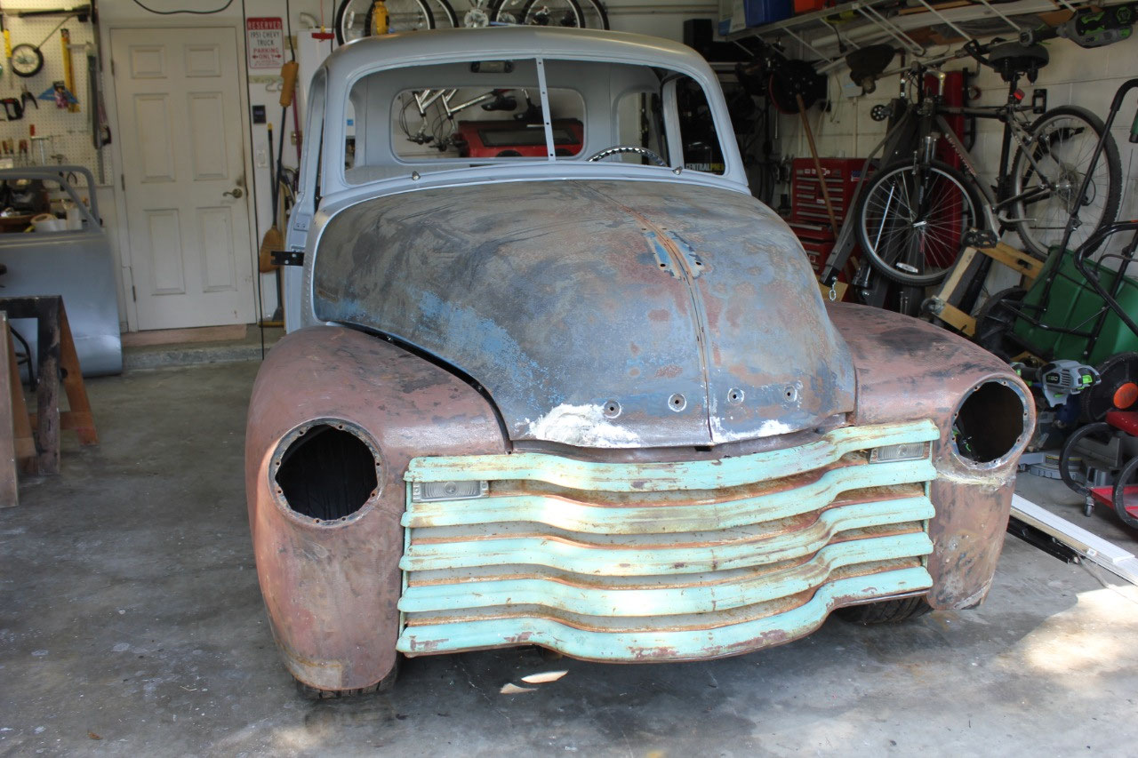
Now that the inner fenders were back installed, I dragged
out the original grille and lower splash pan.
I’d never really looked at these, and assumed both would need to be
replaced with new. After separating the
two, and cleaning up the lower splash pan, it turns out the splash pan is in
surprisingly good shape. It dropped
right in place, along with a couple of bracing rods that tie the splash pan to
the radiator core support. All looks
great and the splash pan holds everything in place. Unfortunately, it does interfere with my
clever horn and siren locations, so they needed to be removed and will need to
be relocated. To prevent any further interference,
I went ahead and installed the grille to see if I could find a good location
for the horns and siren, and also see where I could locate the A/C dryer.
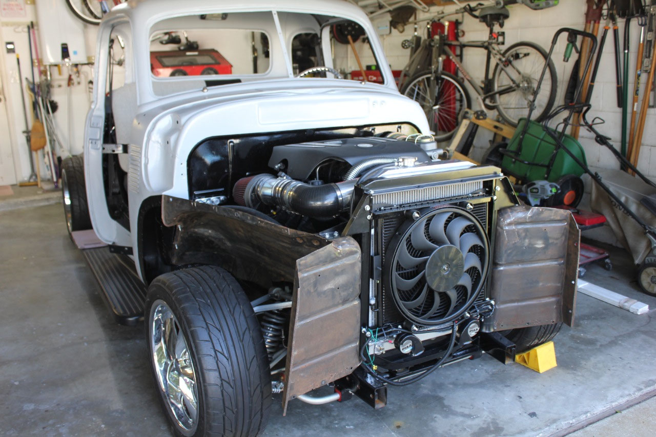
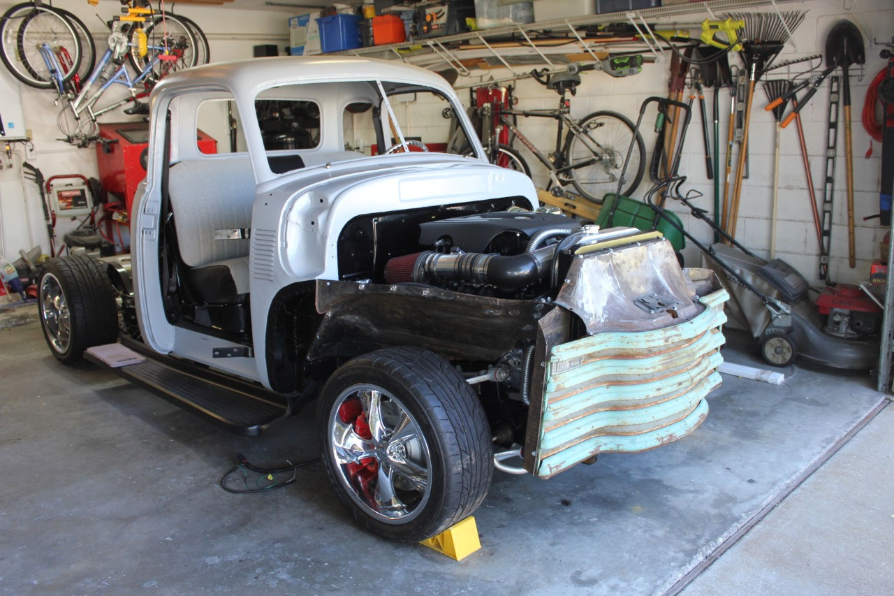
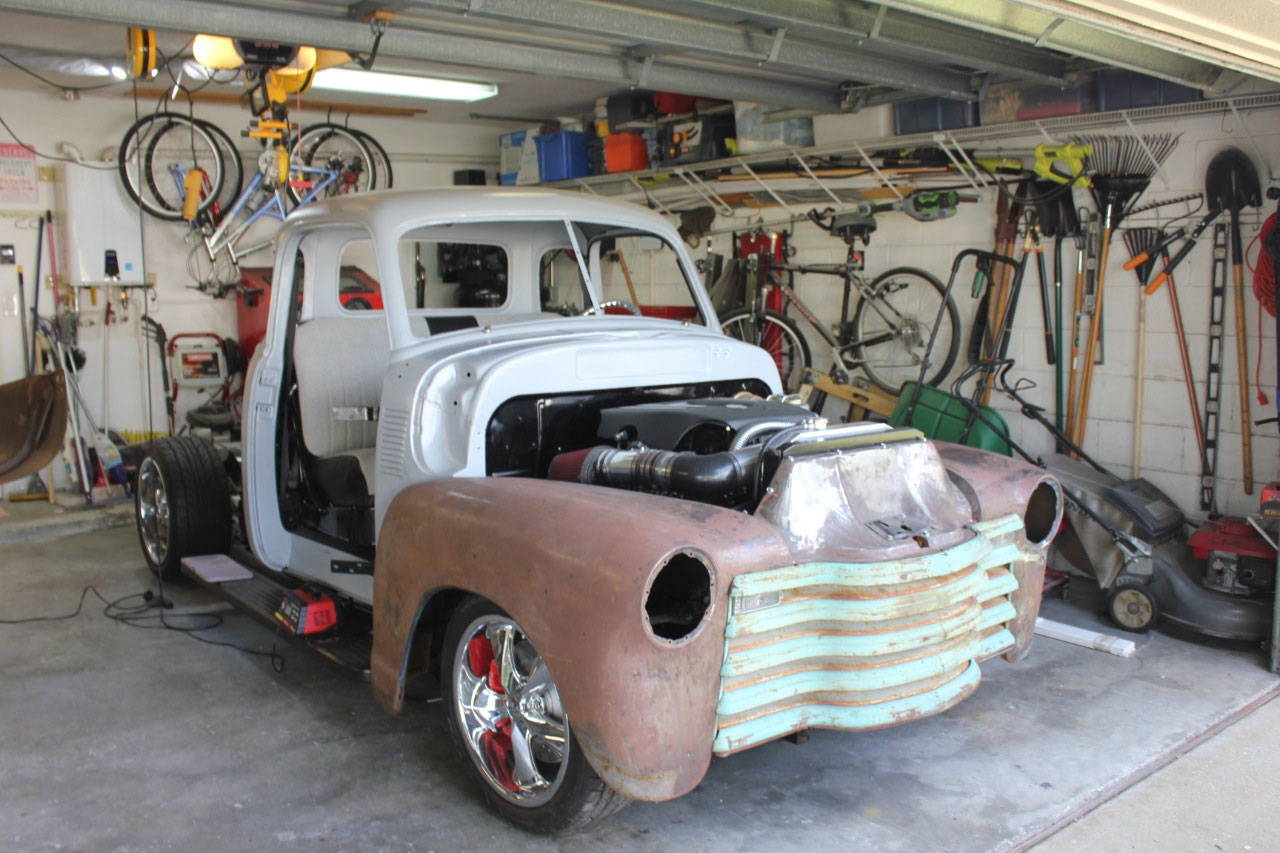
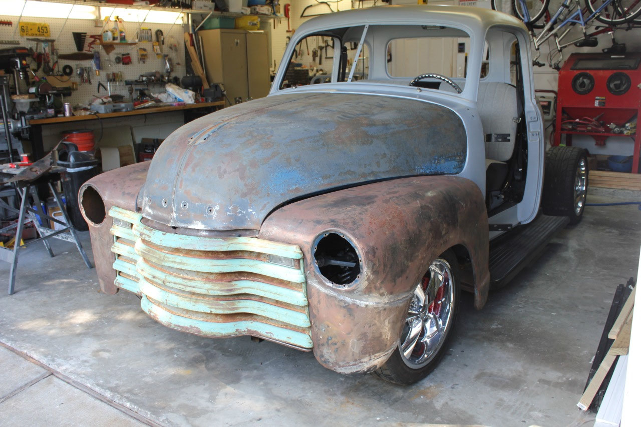
The next installation was the passenger side fender.
This just dropped right in place, with most
of the bolts lining right up. The
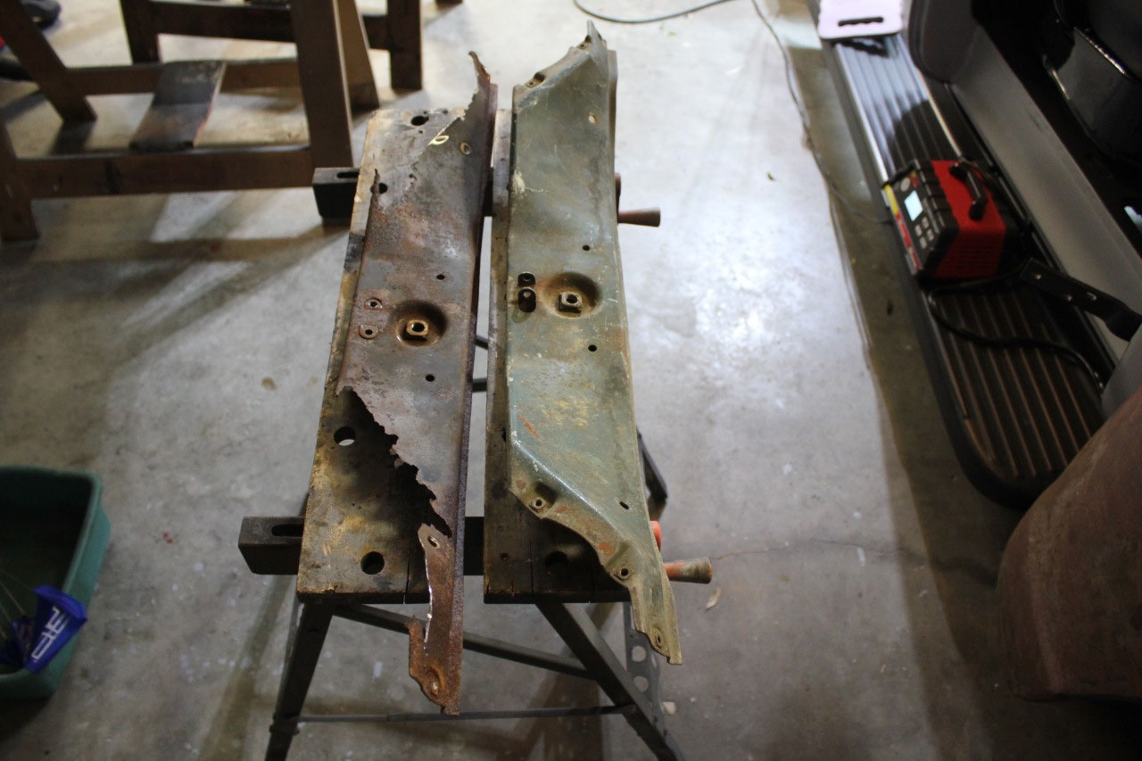
driver’s side fender was a different story.
The rust had been repaired, so it didn’t look too bad, but on closer
inspection, there was a patch panel on the lower front portion of the
fender. When I looked closer, it didn’t
really line up with the curvature of the wheel opening, and it was not vertical
at the grill opening. Luckily, the
previous owner had included the original section that had been removed and
there was only a little rust at the bottom edge. I decided to just cut out the previous
repair, reinstall the original piece, and only replace the small portion that
had the rust. The metalwork came out
pretty good. A little body filler after
media blasting should make it good as new.
The other problem with the driver side fender was the
headlight opening. When I looked close,
it appeared that the headlight opening had been hit in an accident. It was very minor, but the headlight mounting
flange was about ½ inch further back than the passenger side on the outside edge.
Luckily, a little work with a door skin body
hammer, and I was able to get everything back where it belongs. I will need to do a little bodywork after
media blast, but it looks like it will clean up fine.
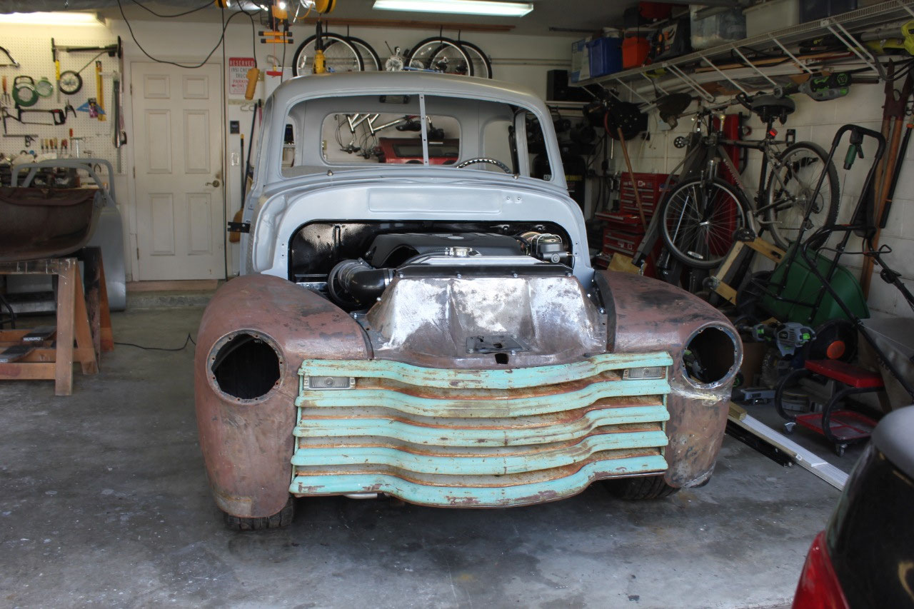
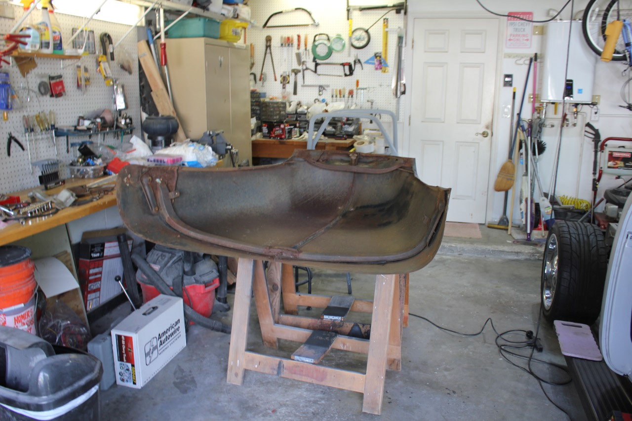
With the front of the truck beginning to look like a real
vehicle, I decided I may as well get out the hood and see what kind of shape it
was in. Hoods have some of the highest
complaints of replacement hoods not fitting, and the cost about $500 plus
freight shipping. So it looks like I
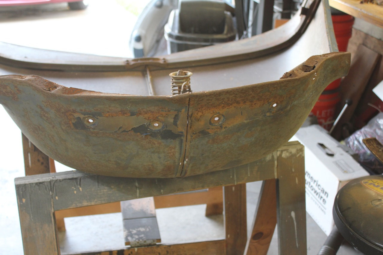
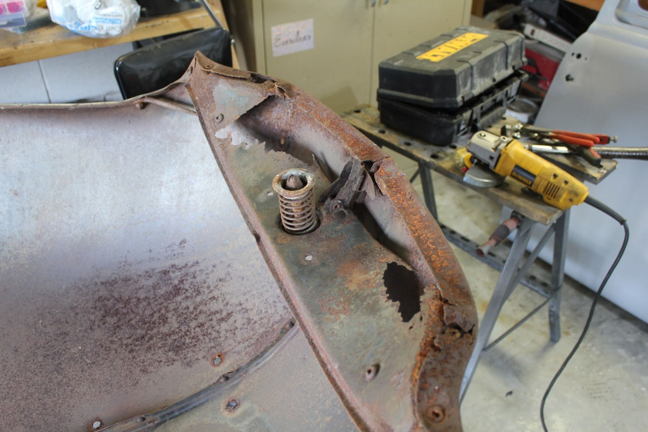
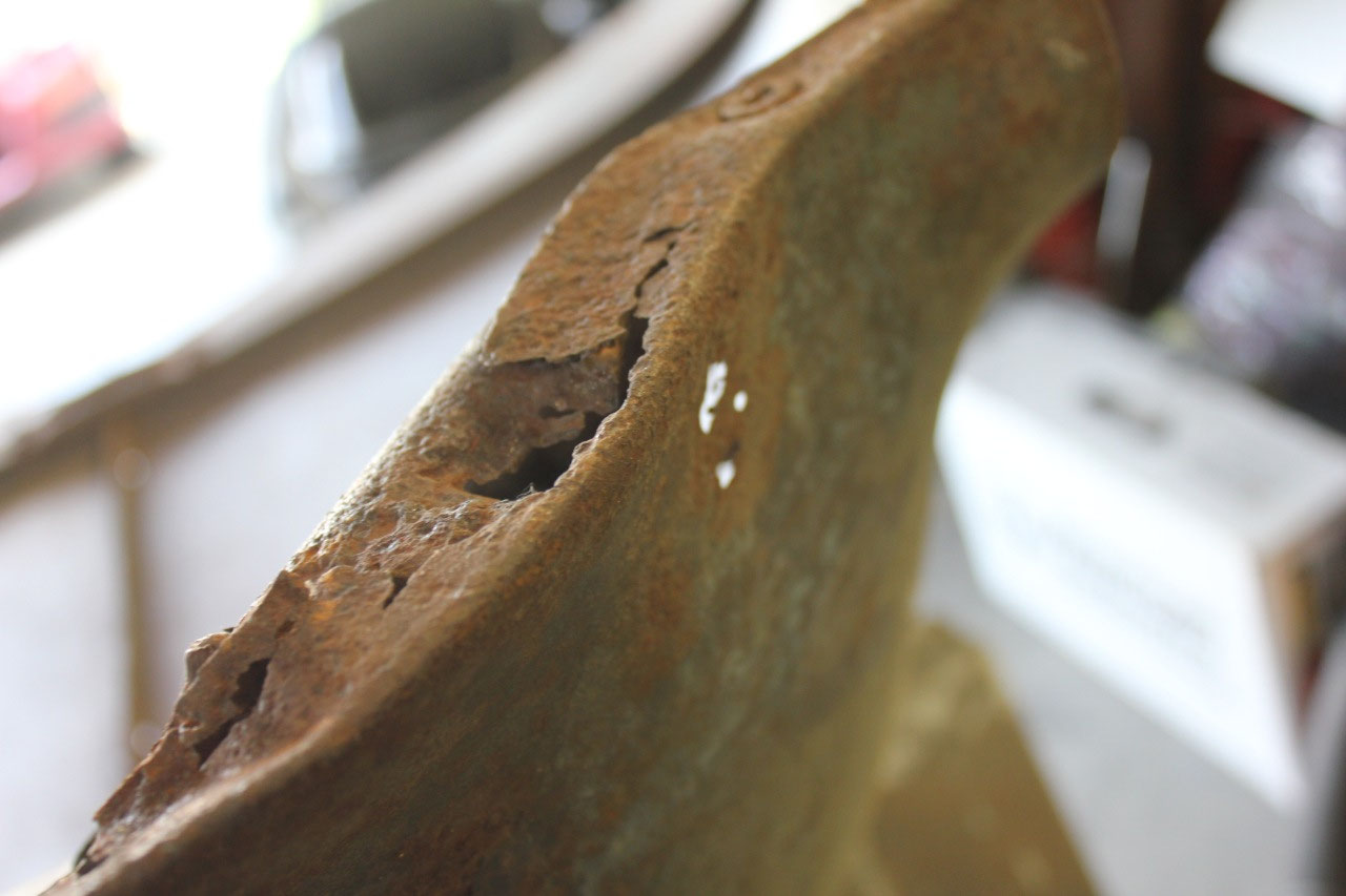
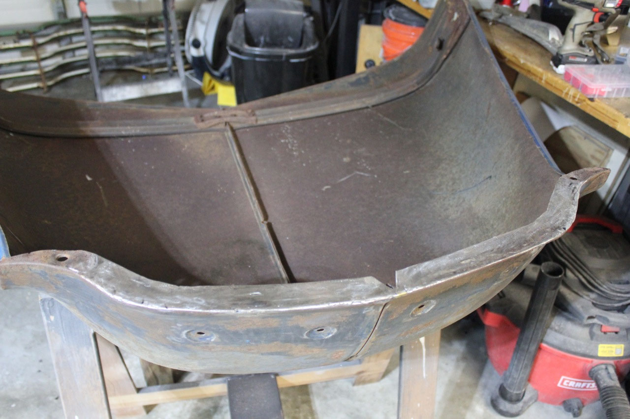
will just need to figure out how to make mine work. The back half of the hood is in great shape
with just a little surface rust, but there is a hood brace across the front
that holds the hood latch pin and spring, and the safety latch that is pretty
much rusted away. There are 2 short rod
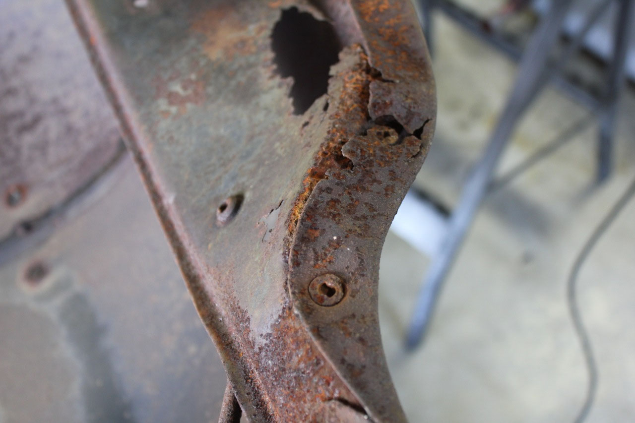
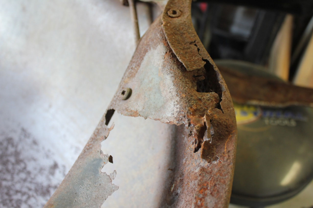
braces, one is good, and the other has a large portion rusted away. The lower edge of the front of the hood is
also rusted away, along with a few rust through holes.
I started by folding up the front lip, tracing a pattern,
and then cutting away the old lip and welding in the new.
The new lip will need to be folded down for
clearance, but I wanted to wait until the hood had been media blasted and
primed before folding it down. That way,
the underside will be protected. It came
out pretty good, and now there is enough strength in the metal to go ahead and
remove the brace. There were supposed to
be 6 bolts and 2 rod braces holding the hood brace in place, but 2 were
completely rusted through, and the other 4 were my favorite clutch head
bolts. I tried to use the clutch head
bolt wrench but eventually gave up and just drilled them out. I also had to drill out the bolts that held
the rod braces in place, but eventually they came out fine.
I tried to find a replacement brace on the internet, and the
only place I could locate a used one was at a shop in Canada for $125 plus
shipping. I did find used rod braces,
but they were typically about $60 plus shipping per pair. I contacted the guy in Canada, and shipping
would be about $38, but he was concerned about getting through customs because
of the coronavirus and could not guarantee a ship date.
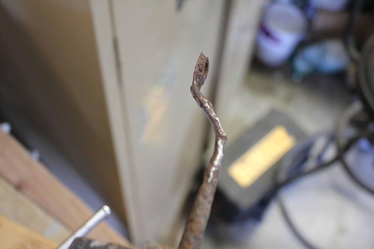
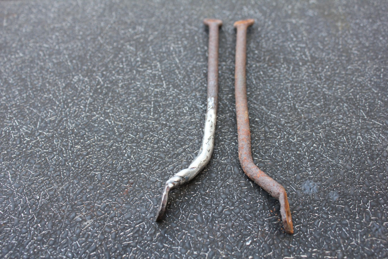
In the meantime, I looked at the short braces
and decided to try fixing the rusted one by building the metal up with
weld. I just took my time and built it
up slowly being careful with the heat until it looked pretty much like the
other. A little grinding on the bench
grinder and it looks great. It just
needs a little paint and it will work fine.
The next night, I was looking around eBay for a used hood
brace, and sure enough one showed up. He
had listed it under a funny name so it took me a while to find. He wanted $119 or best offer with free
shipping from North Carolina. In the
picture it looked great! So I offered
him $100, he accepted, and 2 days later I had it in my hand! It looked even better than the picture! It fit perfectly on the hood. I will probably just run it through my
blasting cabinet, and get some new bolts and all will be well.
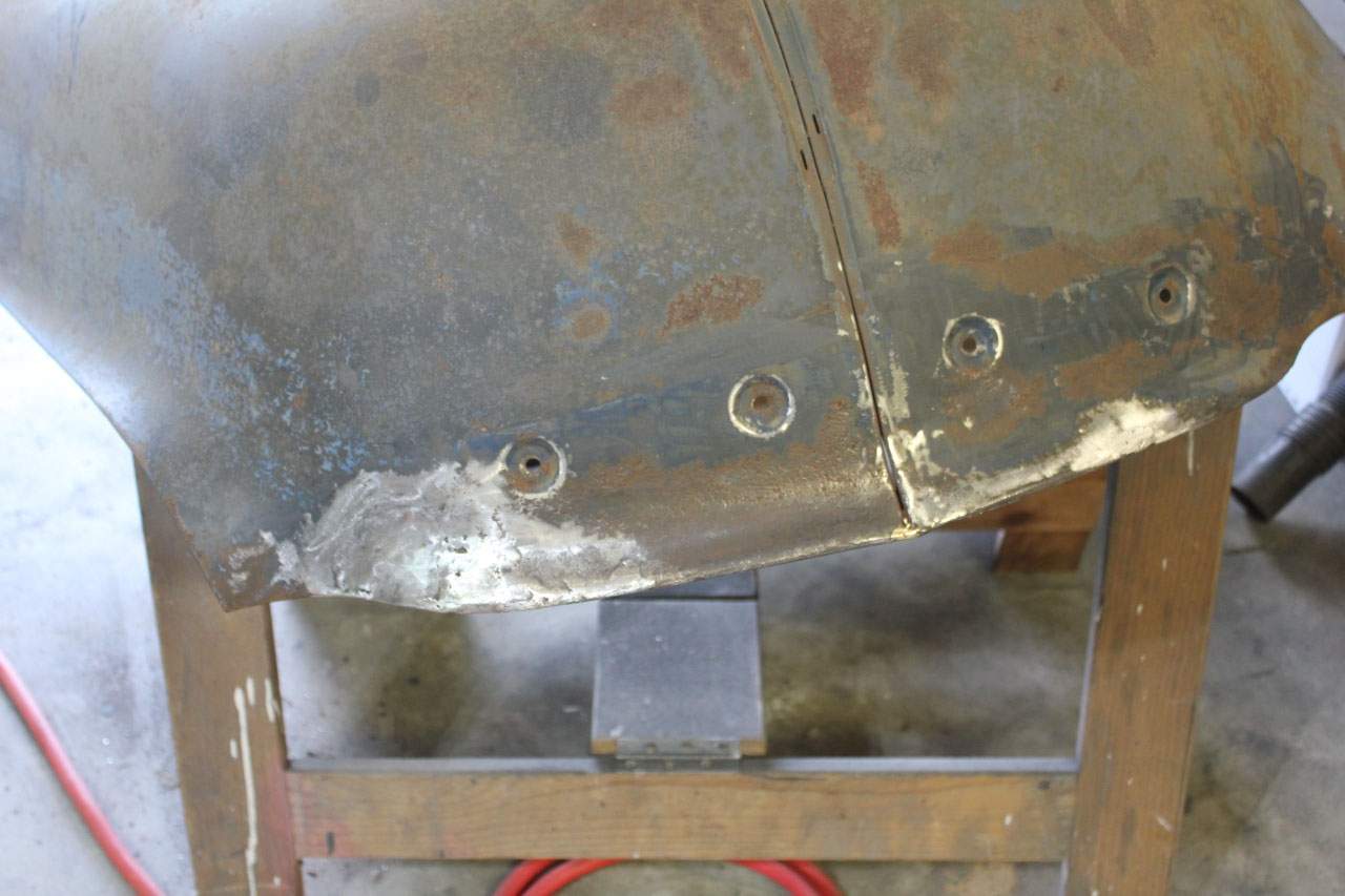
In the meantime, I had done the remaining metalwork on the
hood, and it looks pretty good. It was
difficult to bend up the patch because it was a bunch of compound curves.
But I bent it up close to the correct shape,
tacked it in place and used the hammer and dolly to get the edges to line up
for welding. It’s certainly good enough
that a little body filler will make it good as new.
I did drop the hood in place, mostly for inspiration, rather
than fit. But I did notice that it
didn’t seem to line up all that well and seemed a little short. It took a while to figure out but what I was
doing wrong is that I had tightened up the radiator support and was trying to
get everything lined up to the rigid radiator support. What I need to do after media blast and
primer is to loosen up the radiator support and this should give me more
flexibility to getting everything lined up.
The last step I wanted to do before taking a break and
catching up on the blog was to fit the A/C dryer. I ordered a universal dryer bracket from
Vintage Air, and set about figuring out if I could use any of the hard lines
that came with the condenser kit.
Fortunately, I was able to move the dryer to the left to clear the
pusher fan. The hardlines are made of
aluminum, and can be bent a little by hand.
I was able to use 2 of the original hardlines with a little persuading,
and the third which is the output of the dryer to the evaporator connection
will just be connected with a longer rubber hose.
With this plan in place, I went ahead and
ordered a couple of A/C fittings I needed.
I also ordered a new latch pin, spring, and safety latch. The parts should arrive in a couple of days,
and I should be able to finish up the last couple of tasks (A/C hoses and front
sheet metal wiring harness) and be ready to disassemble the front sheet metal
and send out to be media blasted. I should be able to drive it soon!

2025-05-22