 Orlando, Florida, United States
Somehow, the last time I entered anything into this blog, it
was almost a year ago. Time sure files
in retirement! We returned from our
Hawaii cruise, did one to Cuba, and another to the Caribbean. Suddenly, it was the holidays, and no work
was getting done on the truck. After the
first of the year, I decided to postpone work on the truck and concentrate in
changing the staircase in the house from an ugly painted, carpeted staircase to
cherry wood and wrought iron balusters.
It ended up taking much longer than I had anticipated. Then a cruise, a trip to Italy, a wedding in
New England, and all of a sudden it’s August and a year later! My Facebook page showed me a 1 year memory of
the posting when the cab was media blasted.
I knew it was time to get going.
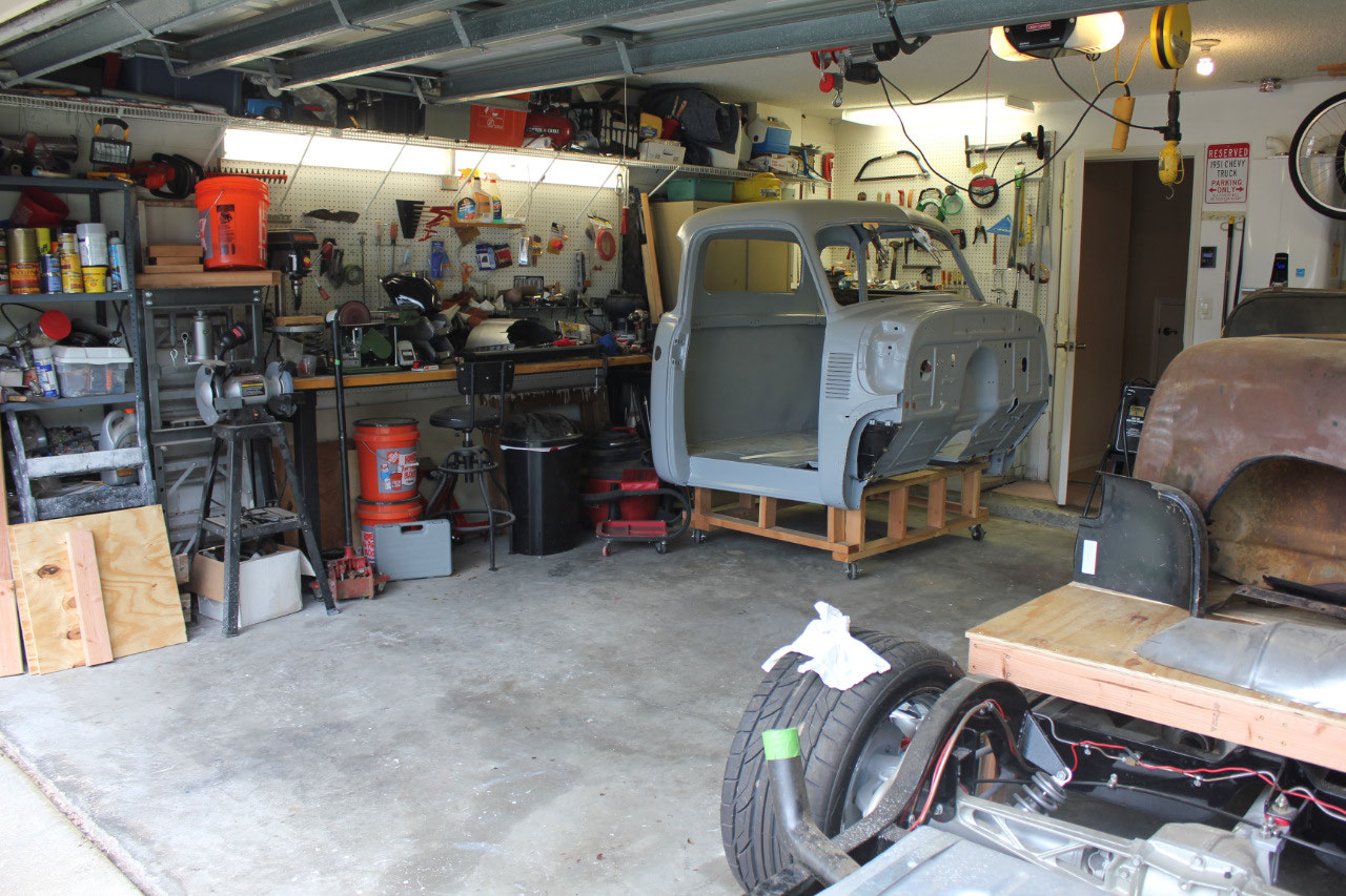
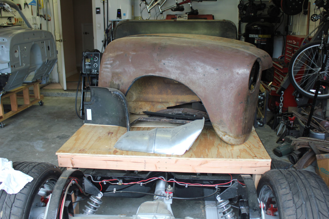
The first step was to figure out where I left off, with the
chassis mostly finished, it was time to tackle the cab. I’ve watched enough car shows to know the
first step in bodywork is to do all the metalwork. This is actually one of the parts I was
really looking forward to doing.
Since
the cab was totally primed in epoxy primer, there was no additional rust since
the media blasting. I cleaned up the
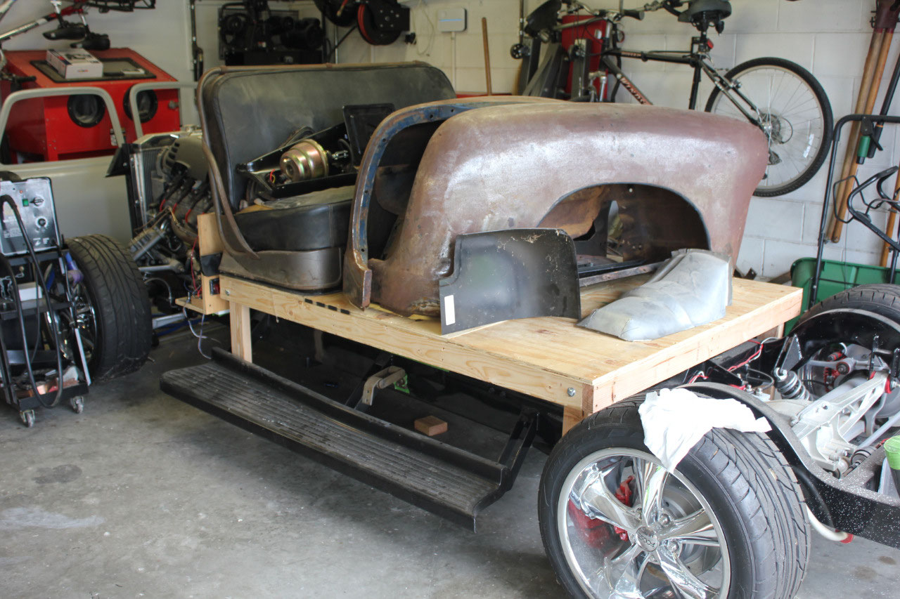
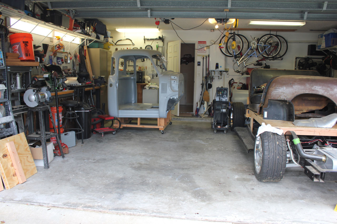
garage, built a wooden table to fit above the chassis, so I could free up some
floor space and give myself some room to work.
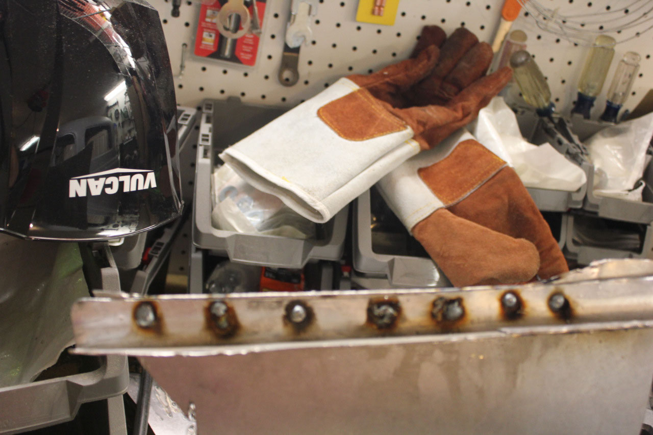
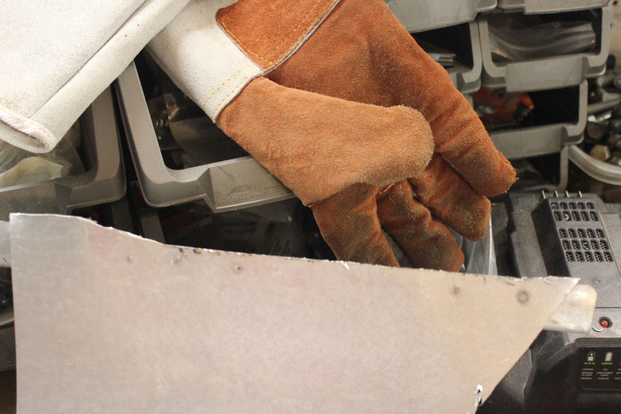
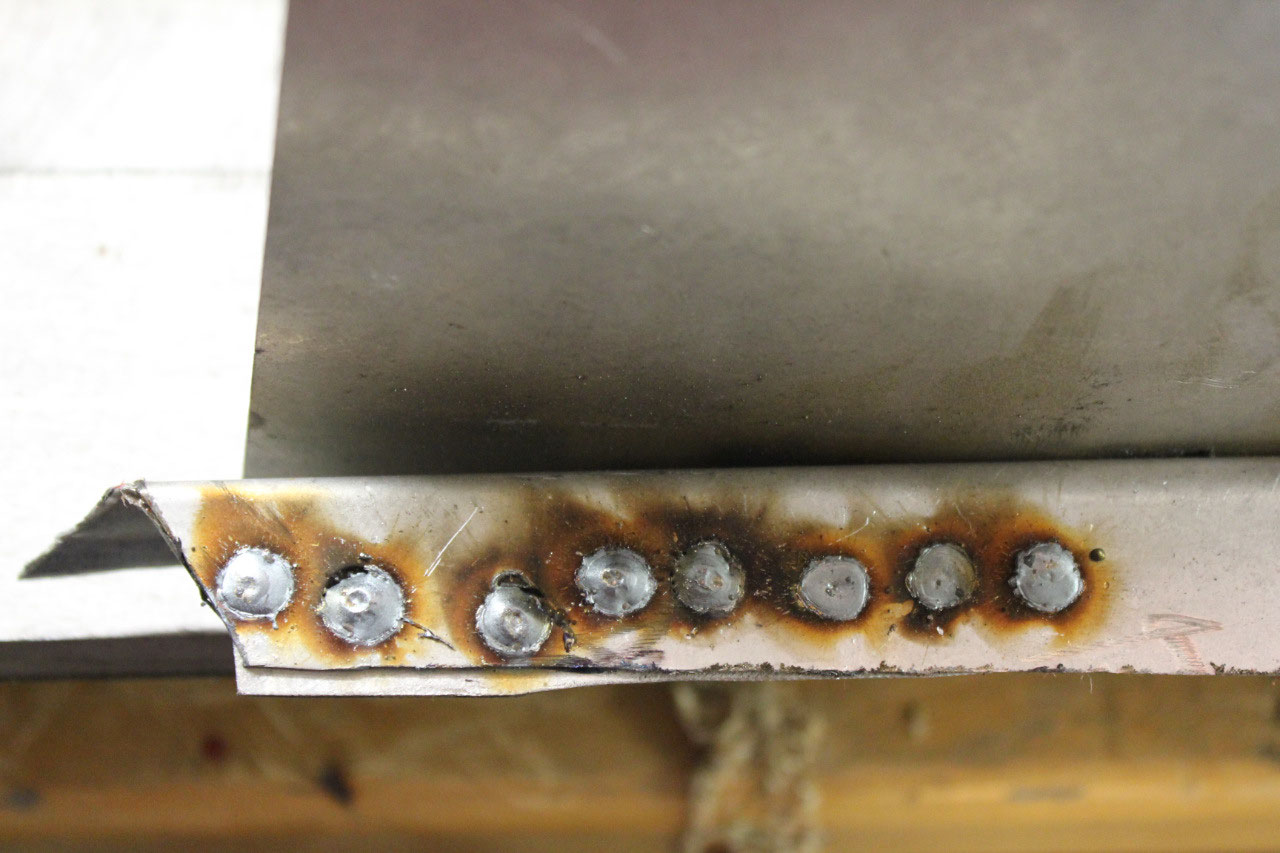
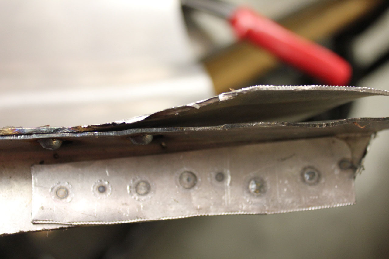
I got out the welder, and practiced some sheet metal technique; running
a bead, butt welding, and plug welding.
Since this is an older truck, all the sheet metal is 18 gauge which is a
lot more forgiving than the newer cars with 20 or 22 gauge metal.
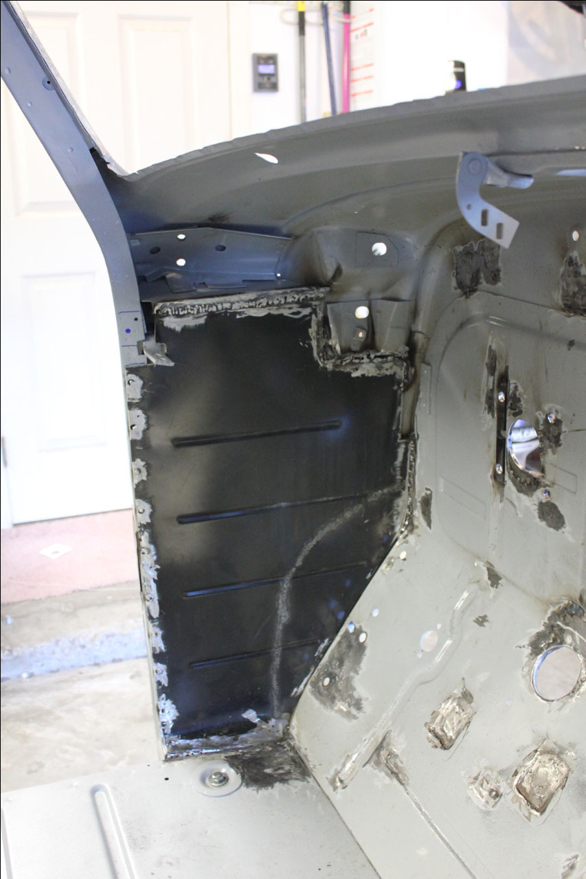
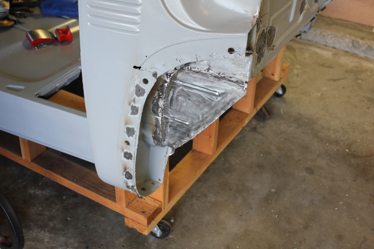
The previous owner had removed several of the sheet metal
pieces in the cab because of rust, but had not replaced them after installing
the floor so that some of the covered areas could be media blasted and
painted. The first of these panes were
the inside kick panels. The driver’s
side panel was partially fit, and the passengers had not been started, so I
began with trimming, bending, hammering the driver’s side panel. It took a while, but it finally started
shaping up. I also got a chance to
checkout my Harbor Freight sheet metal brake to bend a couple of edges and it
worked great! I also got to tryout my
new Cleco fasteners, both the drill through and the pinch type.
They worked well also! I was beginning to look like a professional! After finishing the fitting of the driver’s
side, the passenger’s side kick panel fitting was much easier. Now that the fitting was done, it was time to
break out the welder.
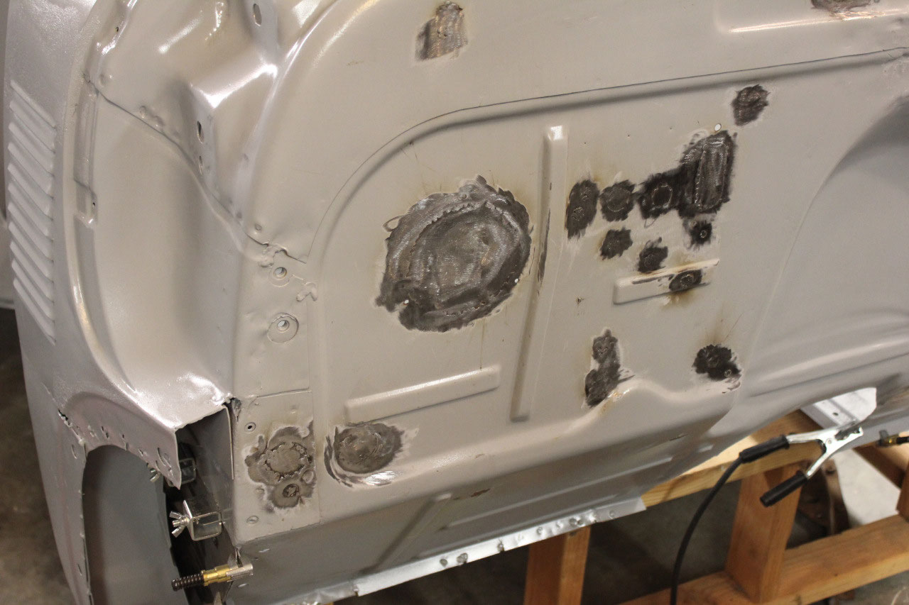
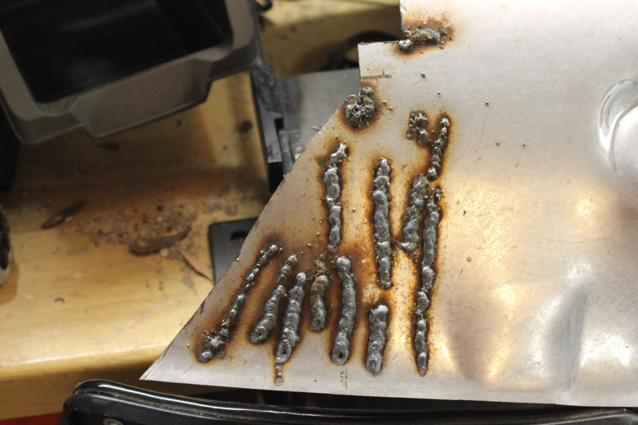
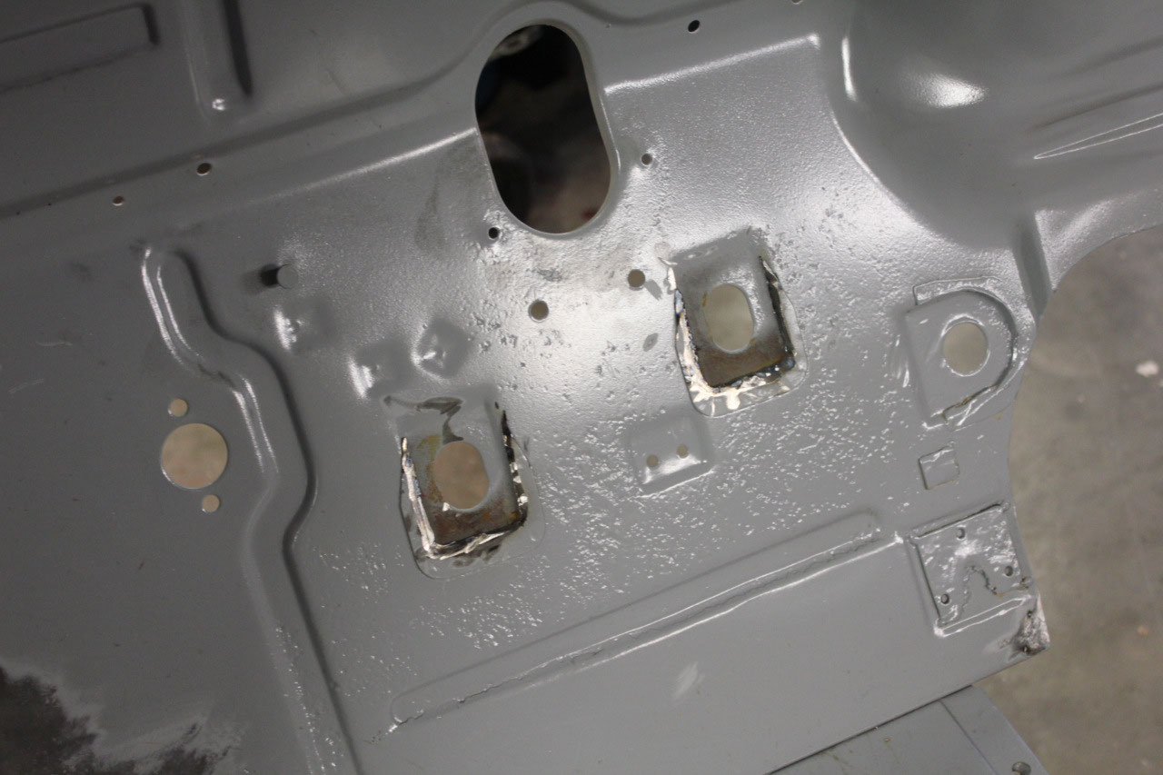
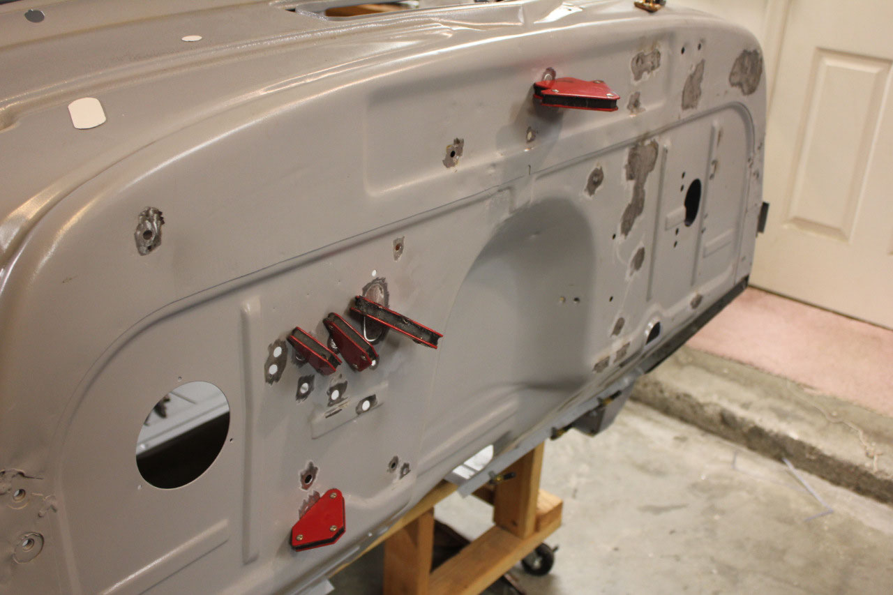
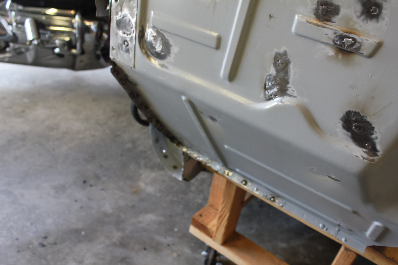
Rather than start welding on the kick panels right away, I
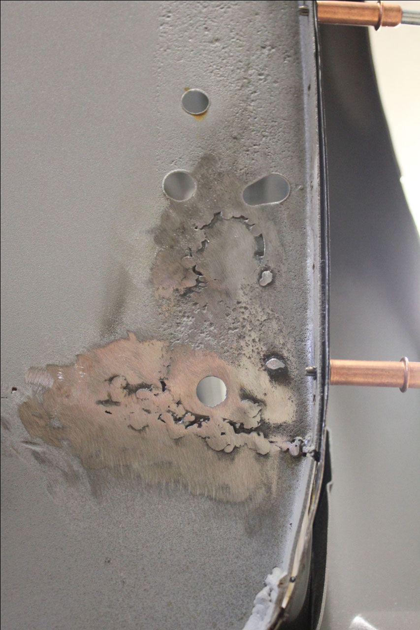
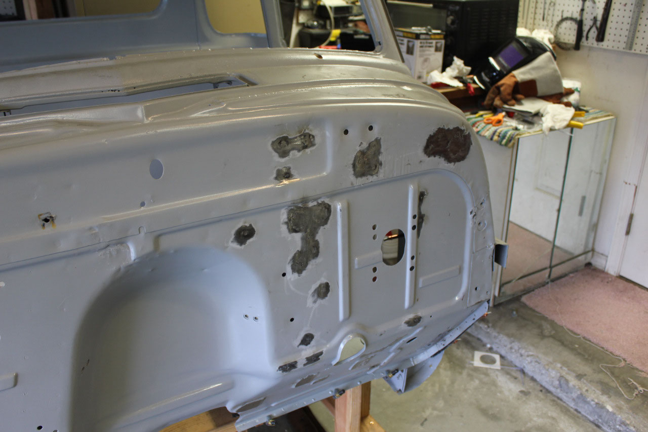
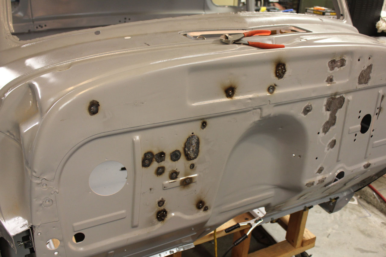
decided to start slowly by filling some of the holes in the firewall and the
floor to build up my confidence in my welding skills. There are about 50 holes in the firewall and
a few in the floor that are used for wires, cables, hoses, bolts, and various
other things in the stock truck. Most of
these are not necessary for this truck, and where possible, I would prefer to
keep the firewall as clean as possible.
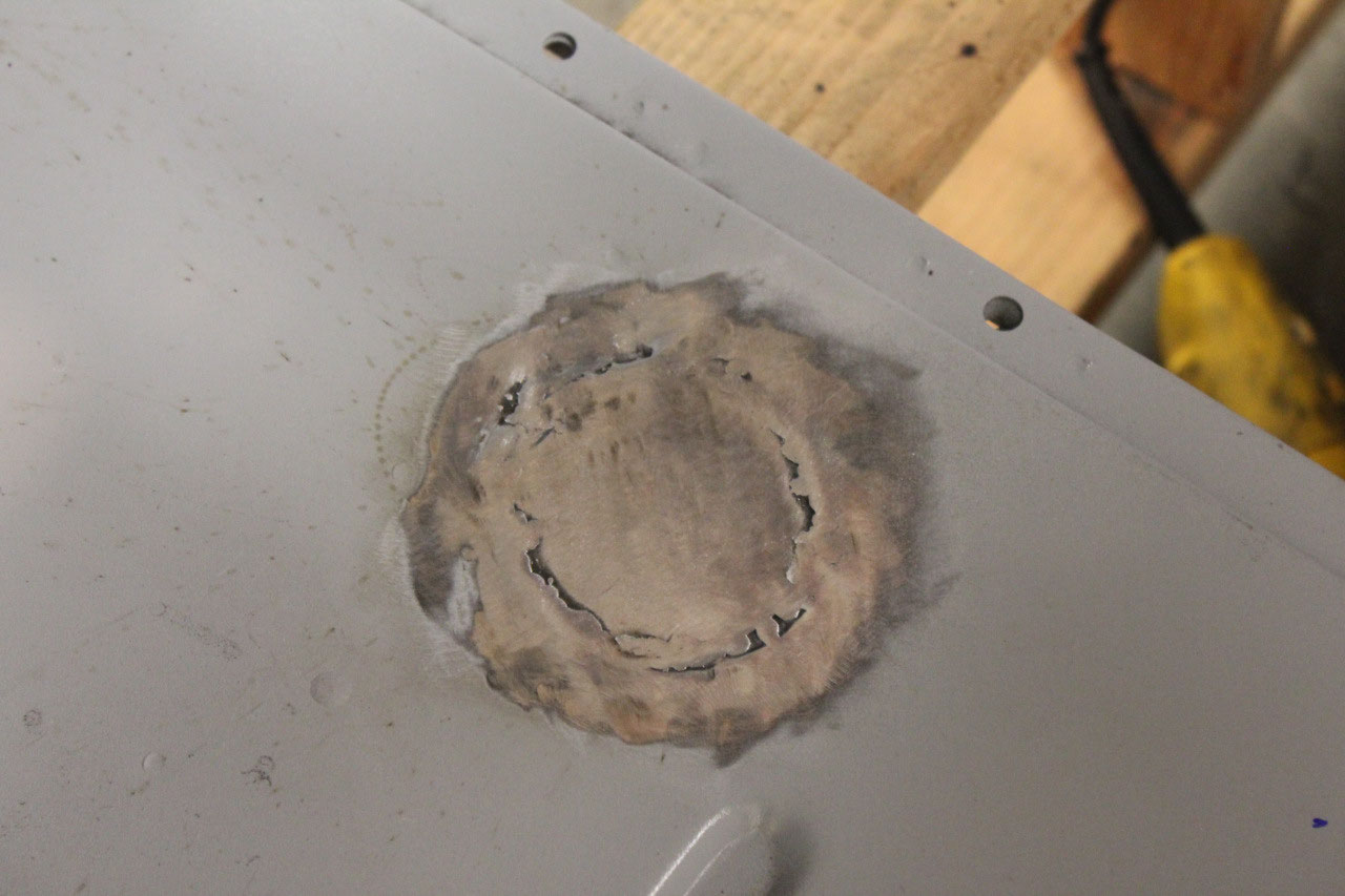
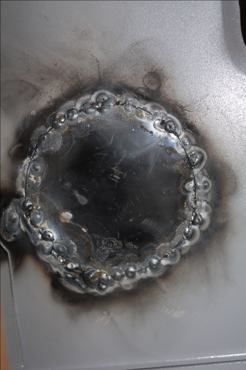
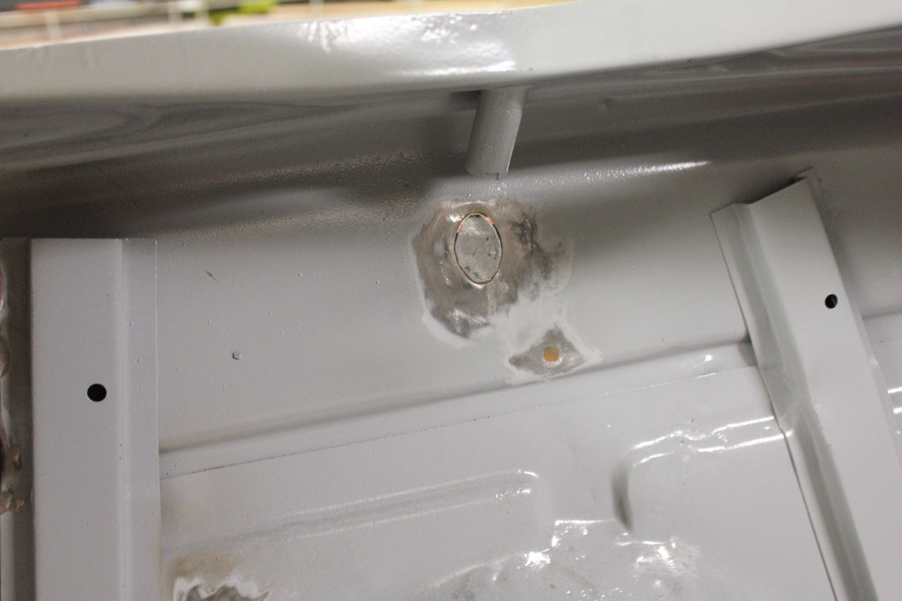
Most of the smaller holes (5/16” or less) can be just filled with
weld. I have a magnetic copper foot that
I can use to cover the hole, and just weld the hole shut. After welding shut, I can then just grind the
weld smooth and the hole is filled.
That’s the theory anyway, but the reality is that it’s harder to do than
I thought, and at first the welds tended to have several pinholes.
I would have to weld, grind, weld the
pinholes shut, grind, weld more pinholes shut, and grind again until the hole
was completely filled. The more I
practiced, the less pinholes, and the less grinding.
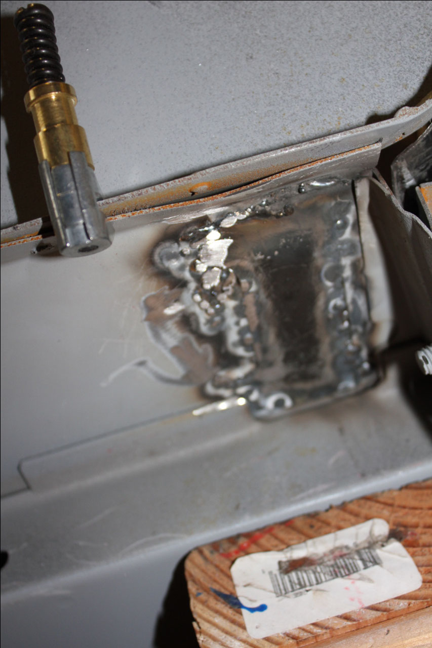
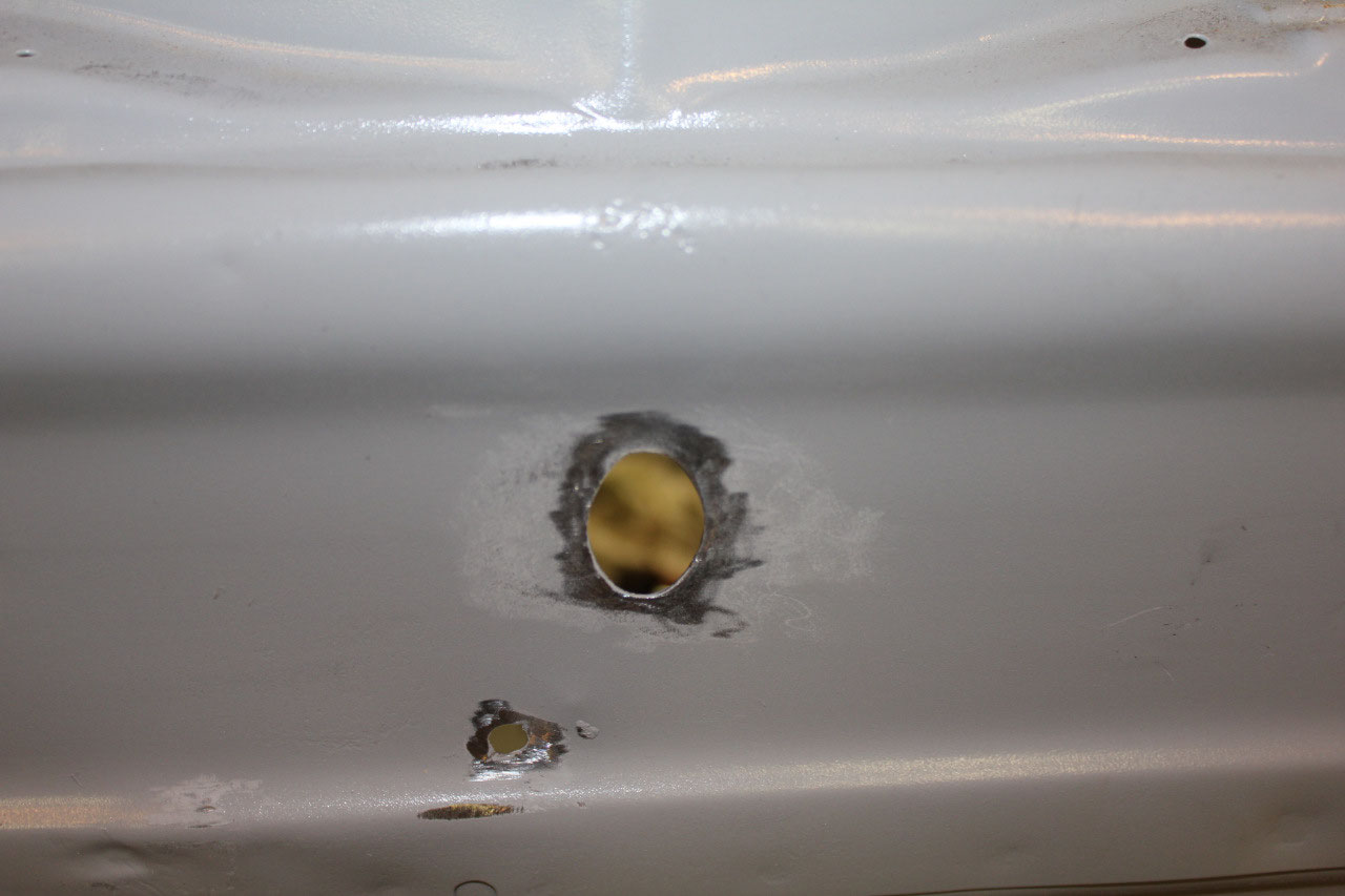
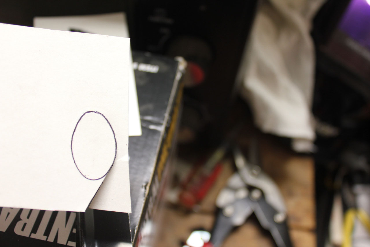
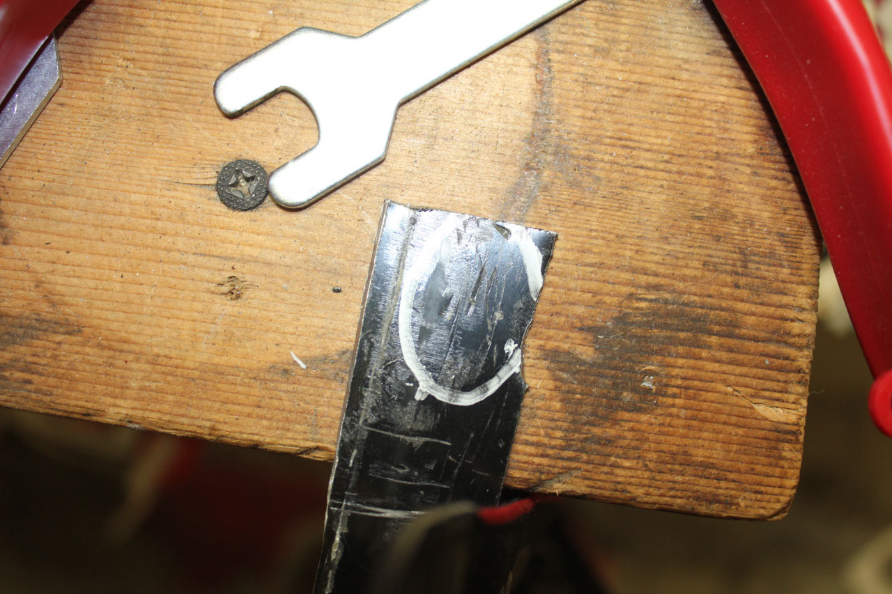
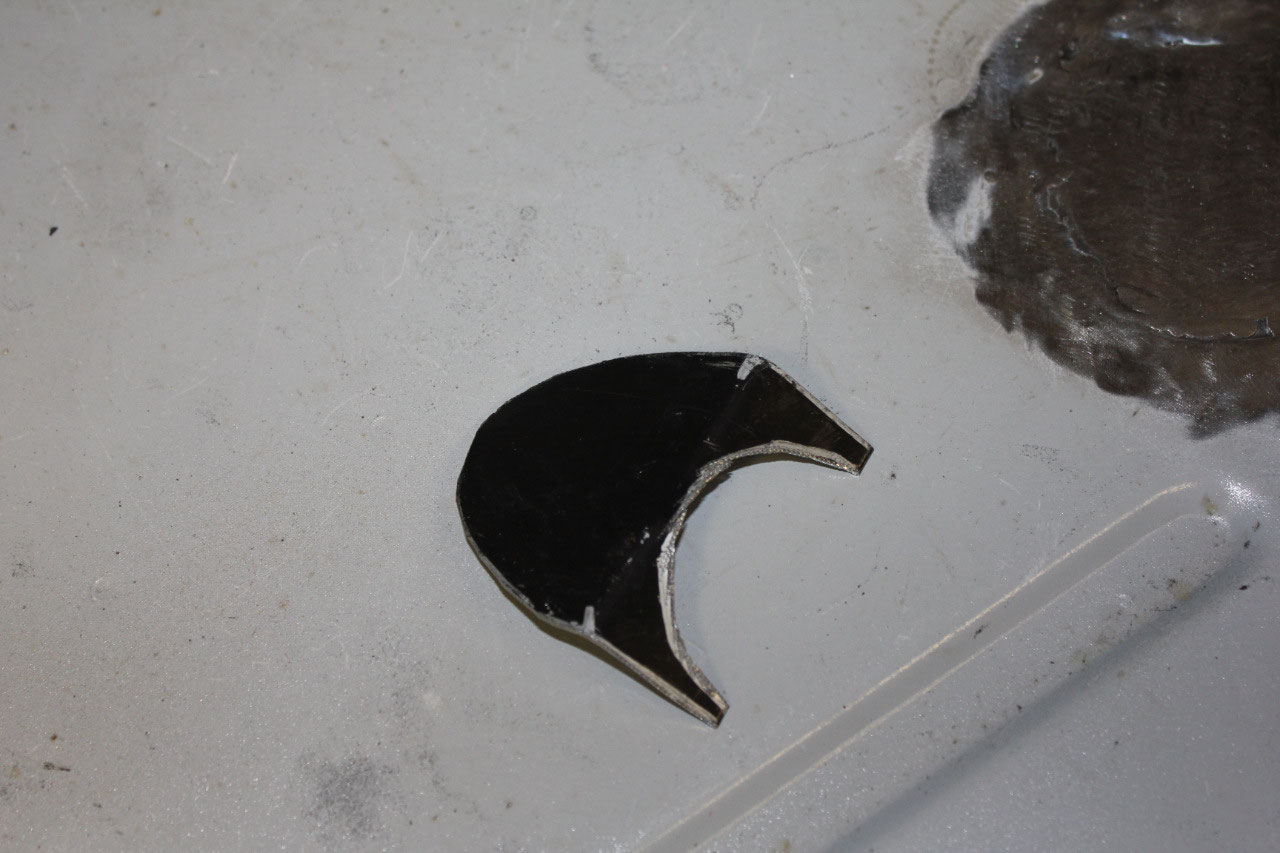
Some of the holes were larger and required a sheet metal
patch. Fortunately, I had some leftover
18 gauge sheet metal from the kick panels and was able to use it to make
patches. The task is tedious, making a
patch template out of cardboard, cutting the sheet metal to match the patch and
then using a magnet to hold the patch in place inside the hole, and butt
welding the patch in place. Since this
is all sheet metal, the butt welding is done by tacking the patch in place in a
few spots and then going back in between the tacks to fill in the spaces. Staying on the metal too long will make it
blow through, and too much heat will warp the panel. So it took some time and practice, but
eventually I was able to weld in the patches with only a few pinholes and much
less grinding than when I started.
Over
the next few days I was able to close up over 50 holes in the firewall and
floor. They are not perfect, but are
close enough that a thin coat of Bondo should smooth everything out. The plan is to finish all the metalwork, and
re-prime any of the affected areas before bring out the Bondo.
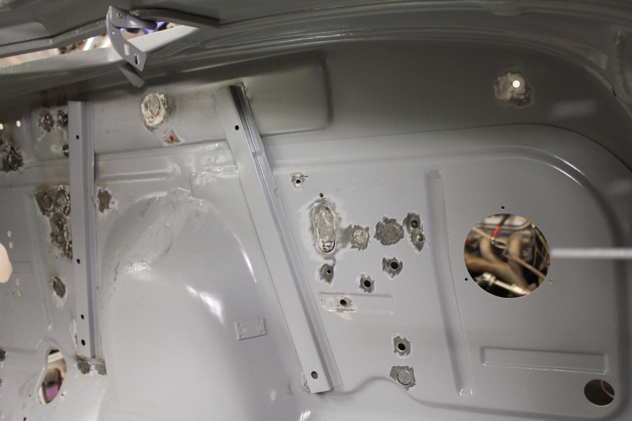
Now that all the unused holes were filled on the firewall,
it was time to make some design decisions.
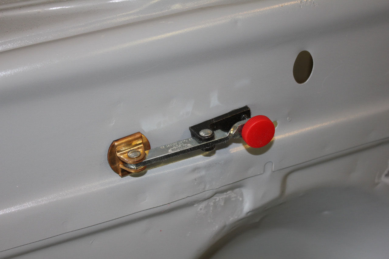
I had seen an ad on the internet for a “power cowl vent” that looked
interesting. There is a vent on the
cowl, between the windshield and the hood that is used to get fresh air into
the cab. I had toyed with the idea of
eliminating it completely, as I don’t really need it with the A/C system, but I
like the way it looks. This kit, made by
Millstone Automotive (www.millstoneautomotive.com)
replaces the mechanical arm that opens the cowl vent with an electrical
actuator and an up/down switch. It looks
cool, but if I use it, I will need to close up a couple of more holes in the
firewall for the mechanical arm bolts.
The cowl has a gasket, but is expected to leak, so there is actually a
drain hose as part of the original design.
Unfortunately, the drain hose just sticks into the engine compartment
and is ugly. So I also need to close up
the drain hole, as I will route the drain hose down through the floor next to
the A/C drain hose.
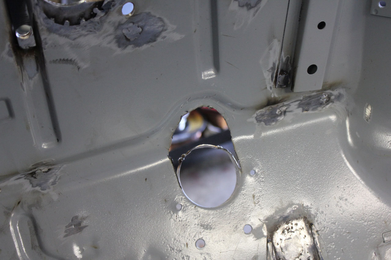
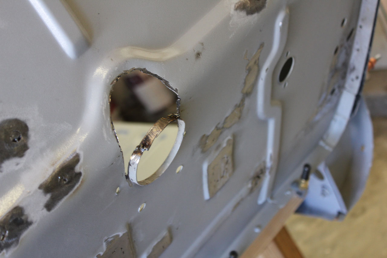
There is also a large hole for the heater motor that is used
by Vintage Air for the heater and A/C hoses, but that is also ugly.
They also sell a straight 4-hose pass through
manifold that looks much better, so the heater motor hole will also be welded
shut. There are a few holes used by
Vintage Air to mount the A/C evaporator that I will leave open. I will need to order the A/C evaporator soon
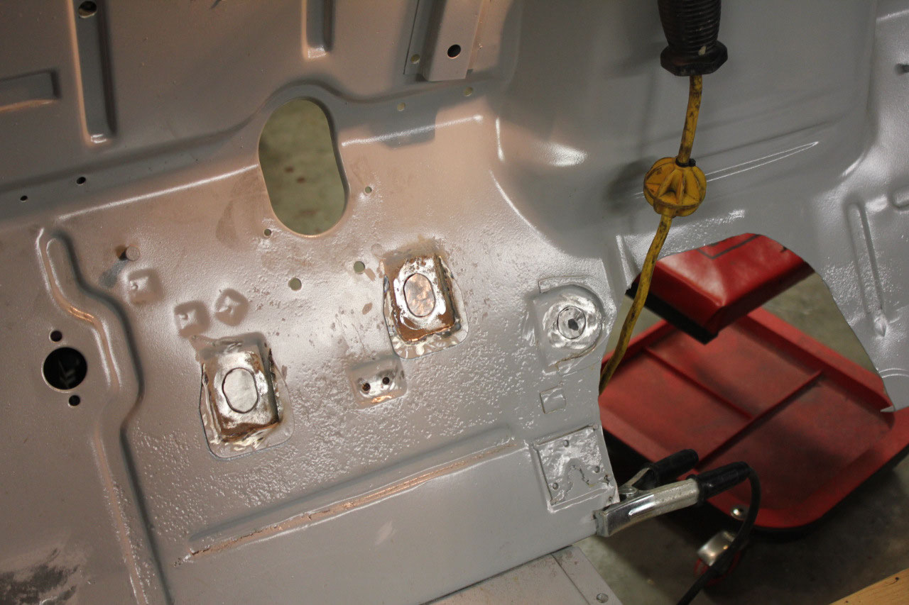
so that I can test-fit the mounting and locate the manifold. Since I am using a firewall mounted master
cylinder, and the master cylinder kit included a couple of thick metal spacers
to make up for bends in the firewall, I decided to go ahead and weld the spacers
in place, both for strength and to make the master cylinder installation easier
down the line.
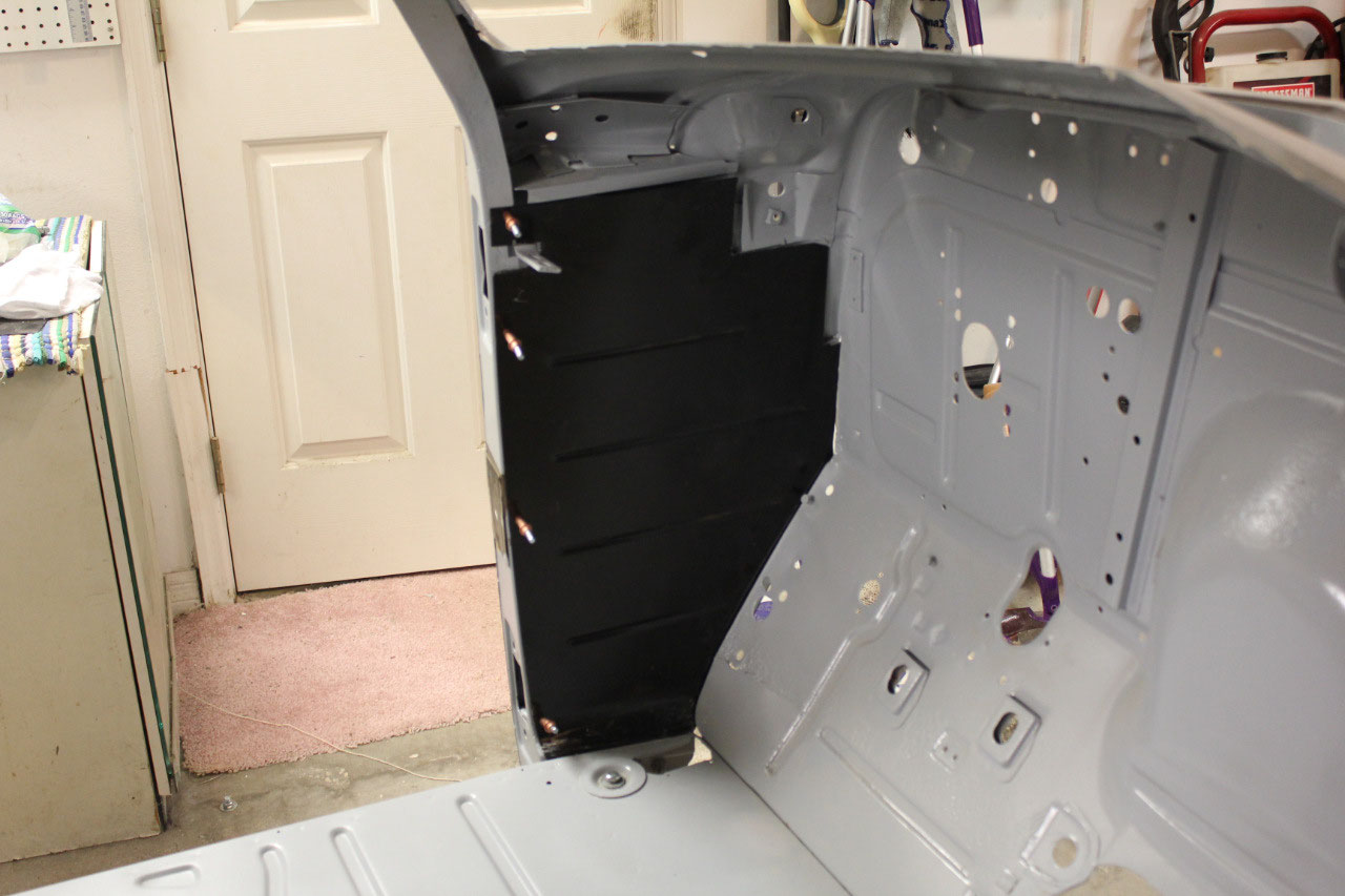
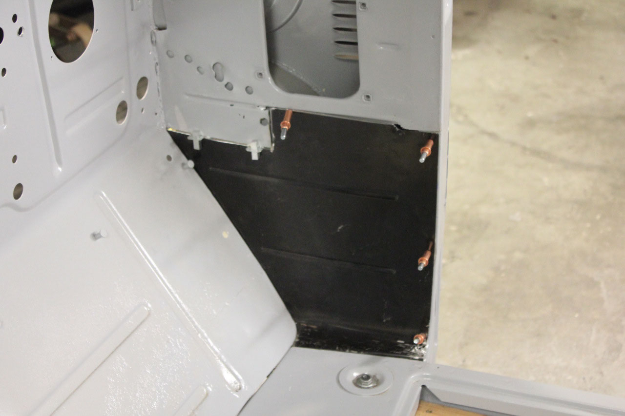
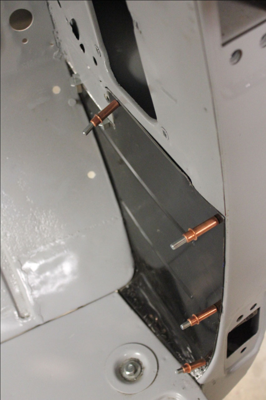
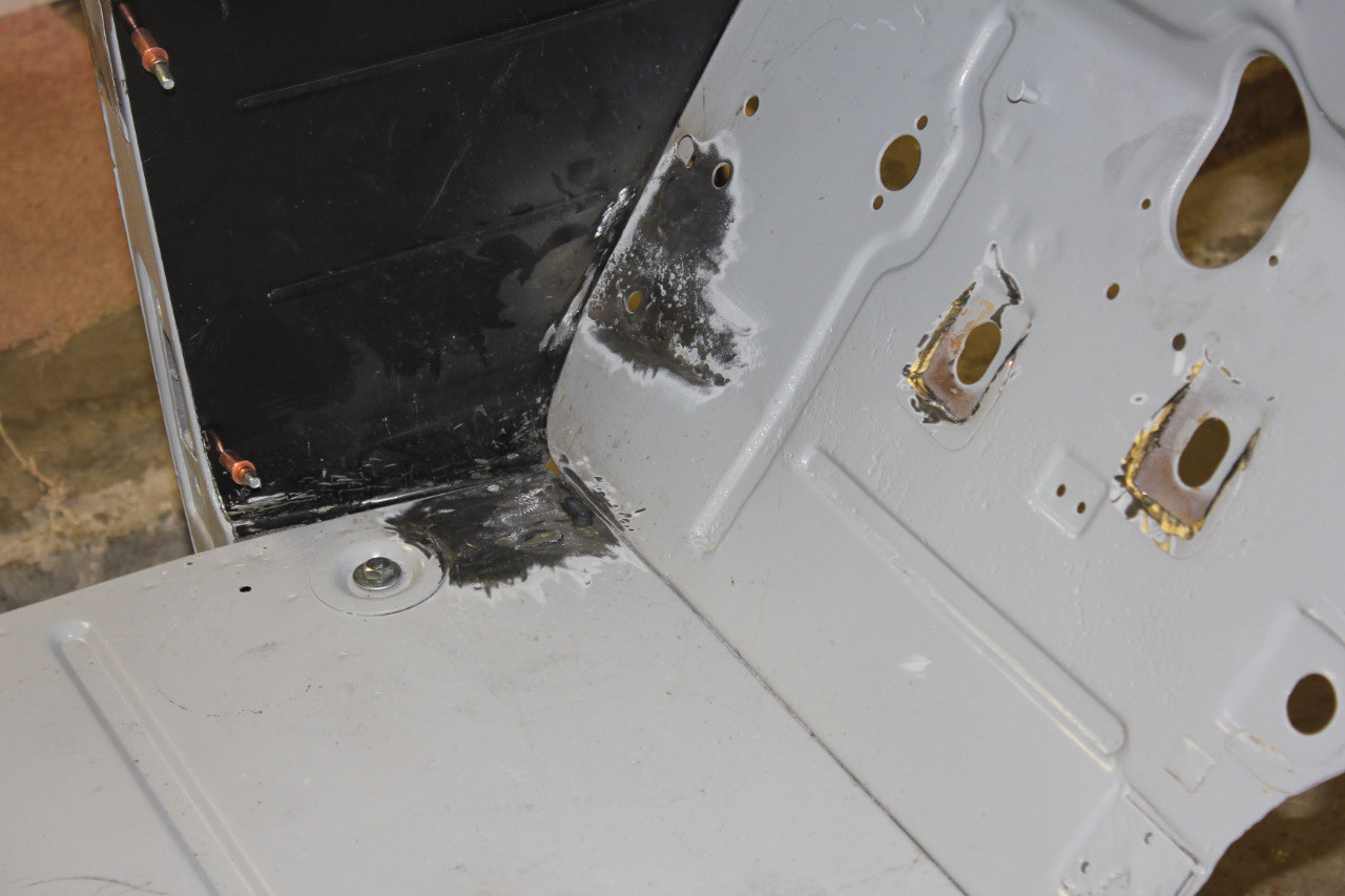
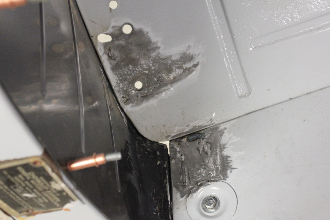
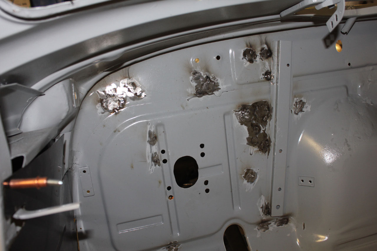
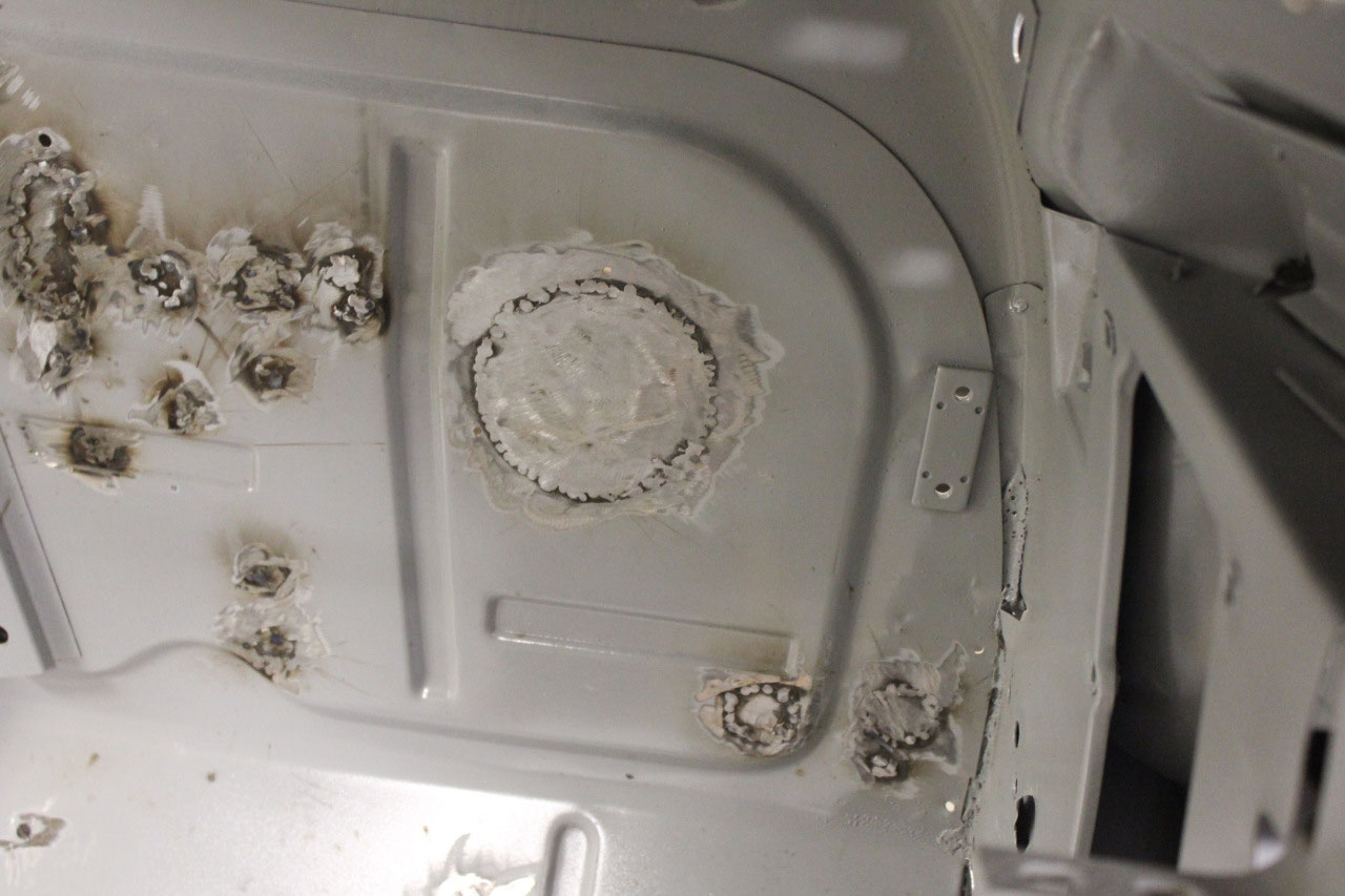
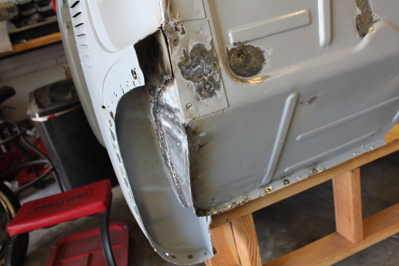
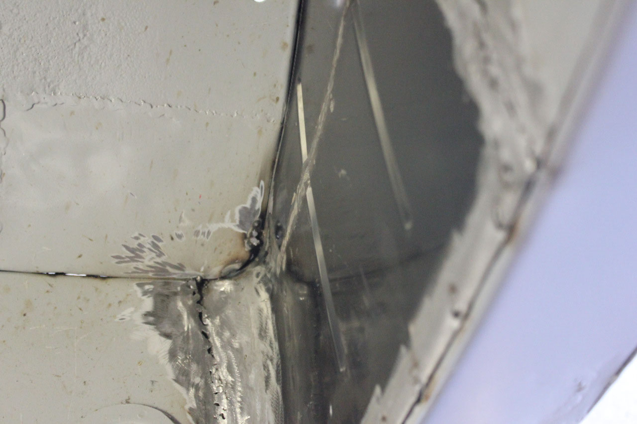
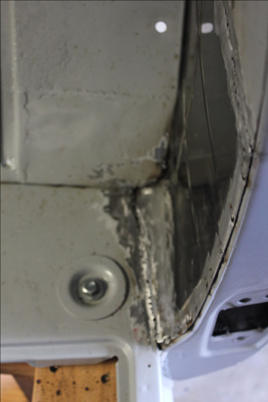
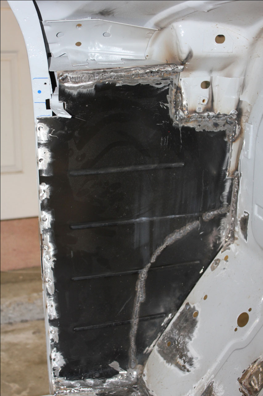
Now that the firewall holes are all plugged, and my welding
skills have improved, it was time to tackle the kick panels. The kick panels don’t look like much, but it
turns out they are actually structural to the cab. The front of the kick panel is plug welded to
the toe panel, the rear is plug welded to the A-pillar, and the bottom is
welded to the floor. The top is butt
welded to the remains of the original kick panel.
But this only attaches the perimeter of the
panel. The most important attachment is
at the center of the panel where the inner lower cowl panel has a c-channel
that attaches from the front fender mounting bolts on one side and this
c-channel welds to the kick panel to transfer the load to the A-pillar and the
floor. I did have some trouble with a
gap between the c-channel and the kick panel, but a little bending and hammer
work closed the gap right up.
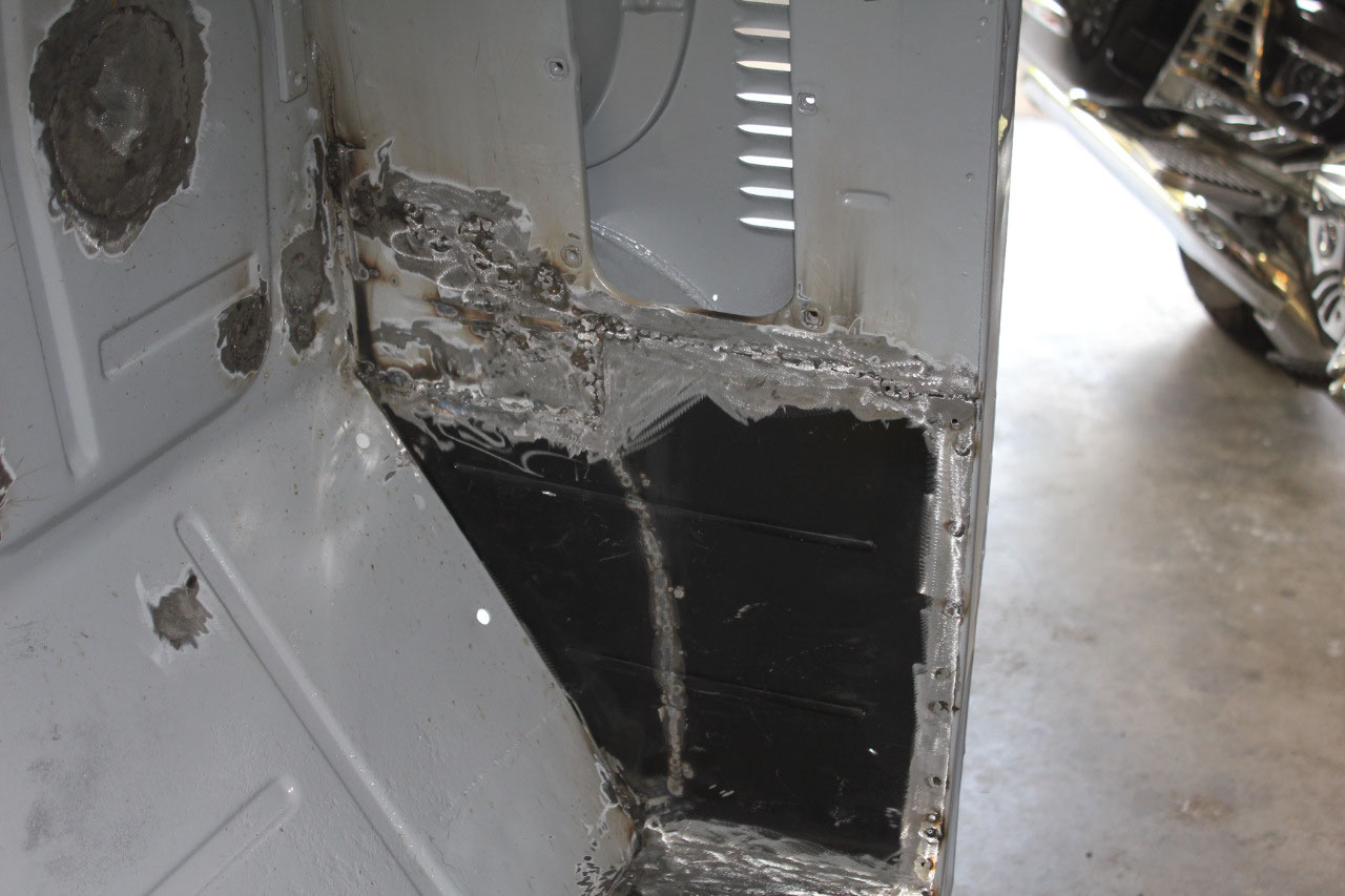
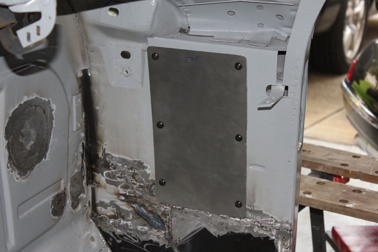
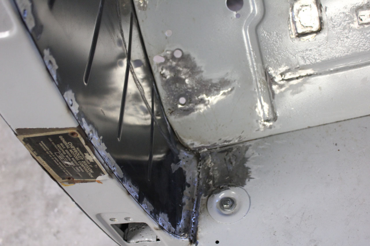
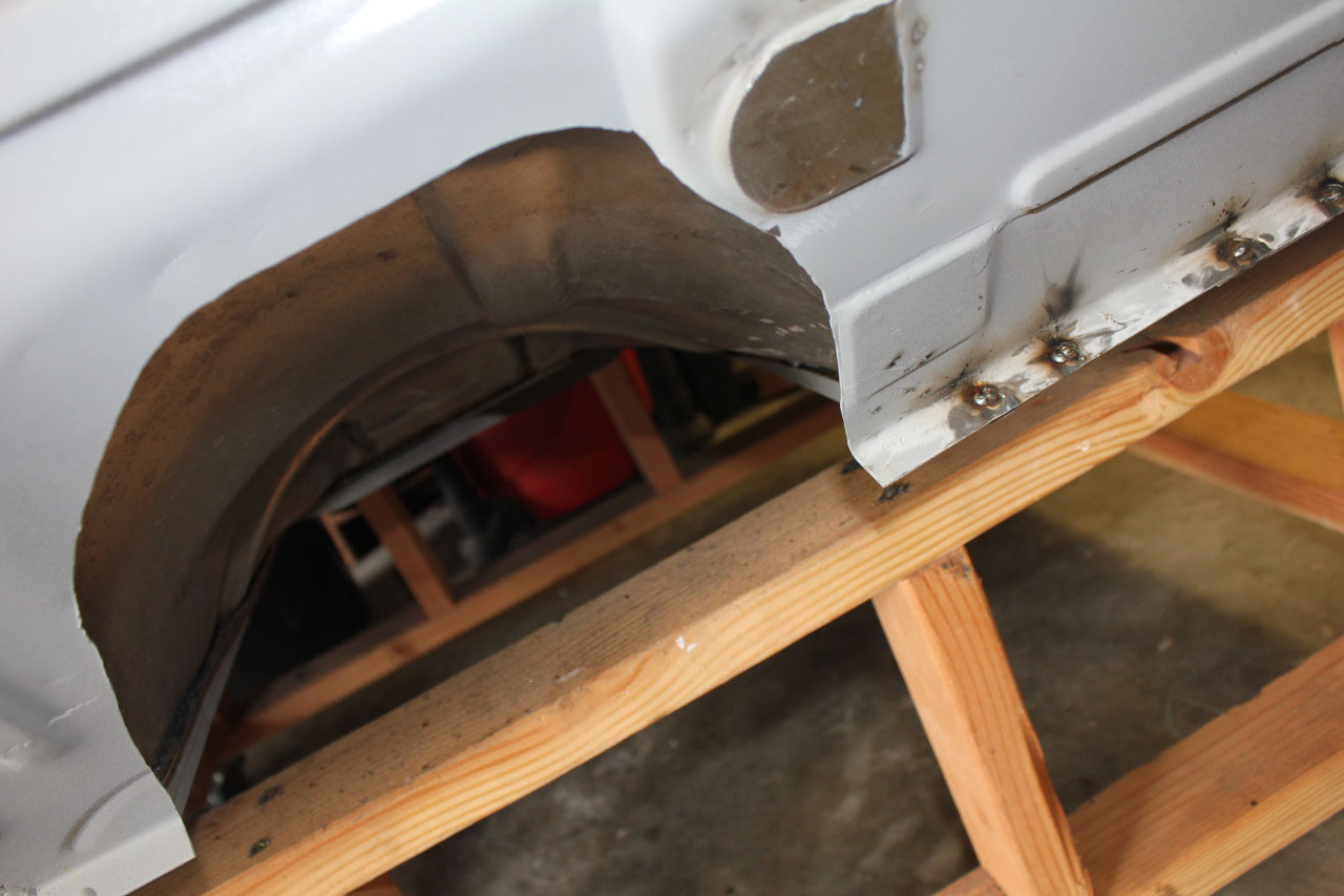
The kick panels came out great, and the cab is really
starting to take shape. The right kick
panel has a large opening for a heater, but for this application, I just needed
to make up a sheet metal cover. I used a
piece of 16 gauge sheet metal from Home Depot and made my own cover. It was pretty straightforward, but getting
the 6 holes in the exact right location was a little tricky. But once I got the cardboard pattern to fit
correctly, it was nothing to transfer it to metal. One of the blind nuts fell out during this
process, but I just happened to have some ¼-20 rivnuts and the tool, so it was
easy to fix.
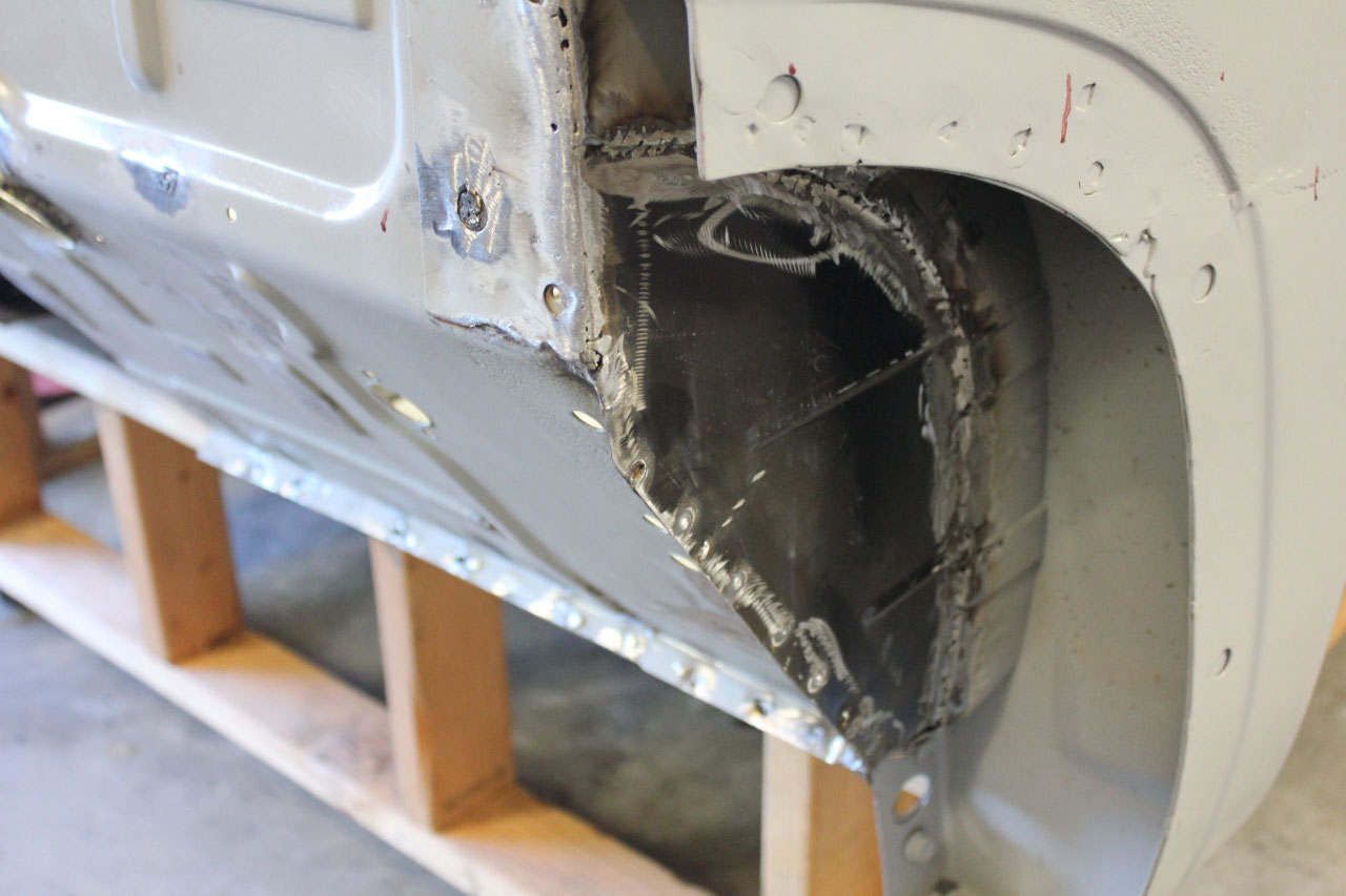
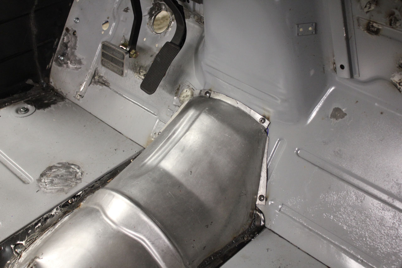
The next step was to tackle the transmission tunnel. The original truck had a flat floor with a
removable transmission cover. Since I
needed a little more room for the 6L80E automatic, I had cut into the
transmission cover and shaped a universal transmission tunnel to fit. Now that it was welding time, I set it all in
place, tweaked the tunnel in a few places and welded the tunnel to the cover. Once the two pieces were welded together, I
was able to cut some more of the transmission cover away to give a little more
room. I also drilled some bolt holes
where the tunnel attaches to the toe plate and welded some ¼-20 nuts to toe
plate to make attachment easier. Most of
these trucks I have seen tend to weld the tunnel in place and make it
permanently attached. My tunnel is still
removable, and should make it easier to work on the linkage and wiring from the
top rather than crawling underneath.
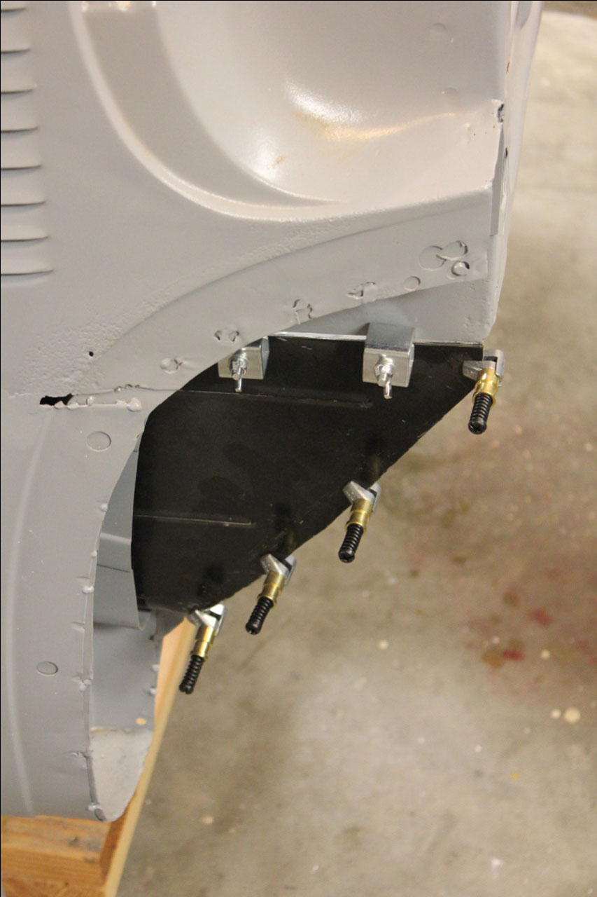
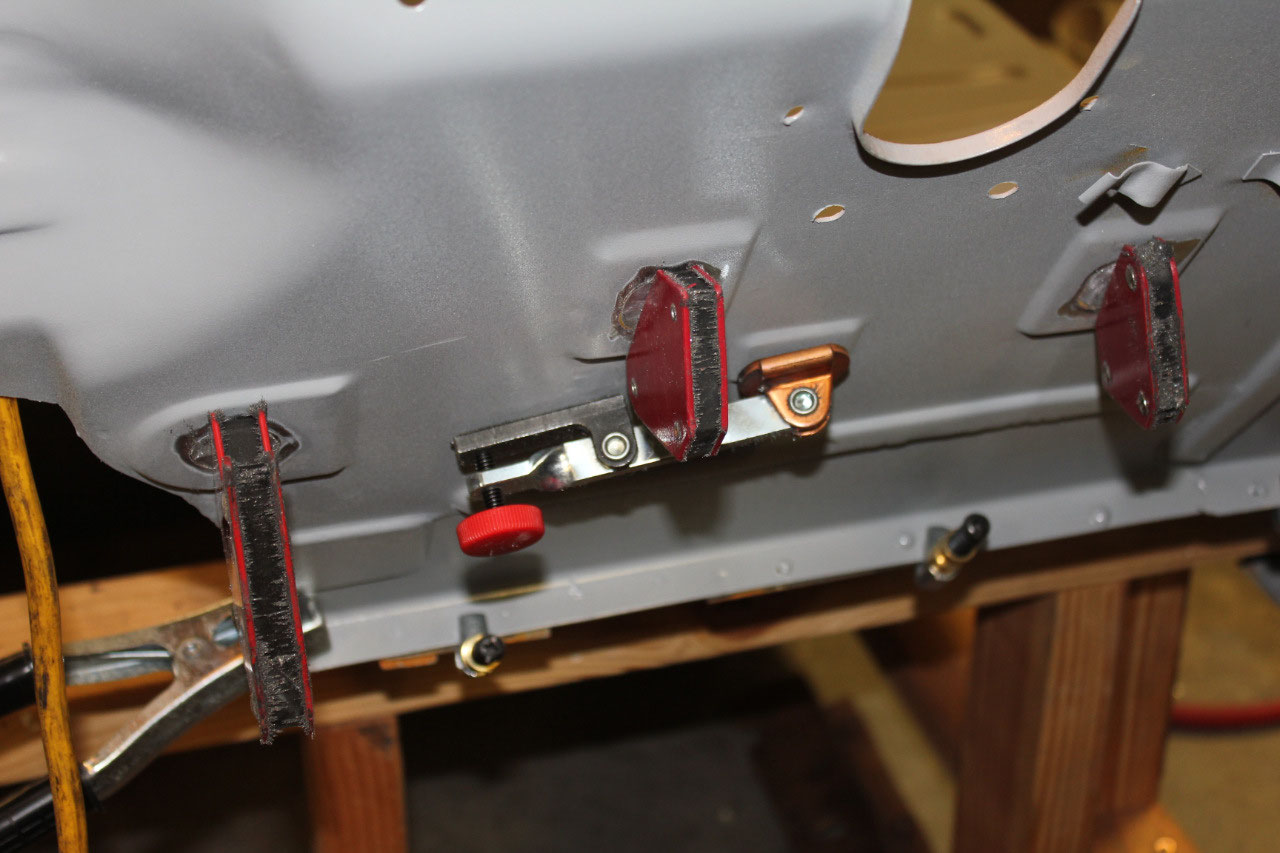
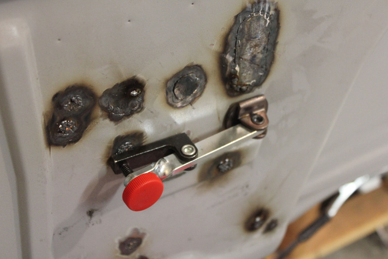
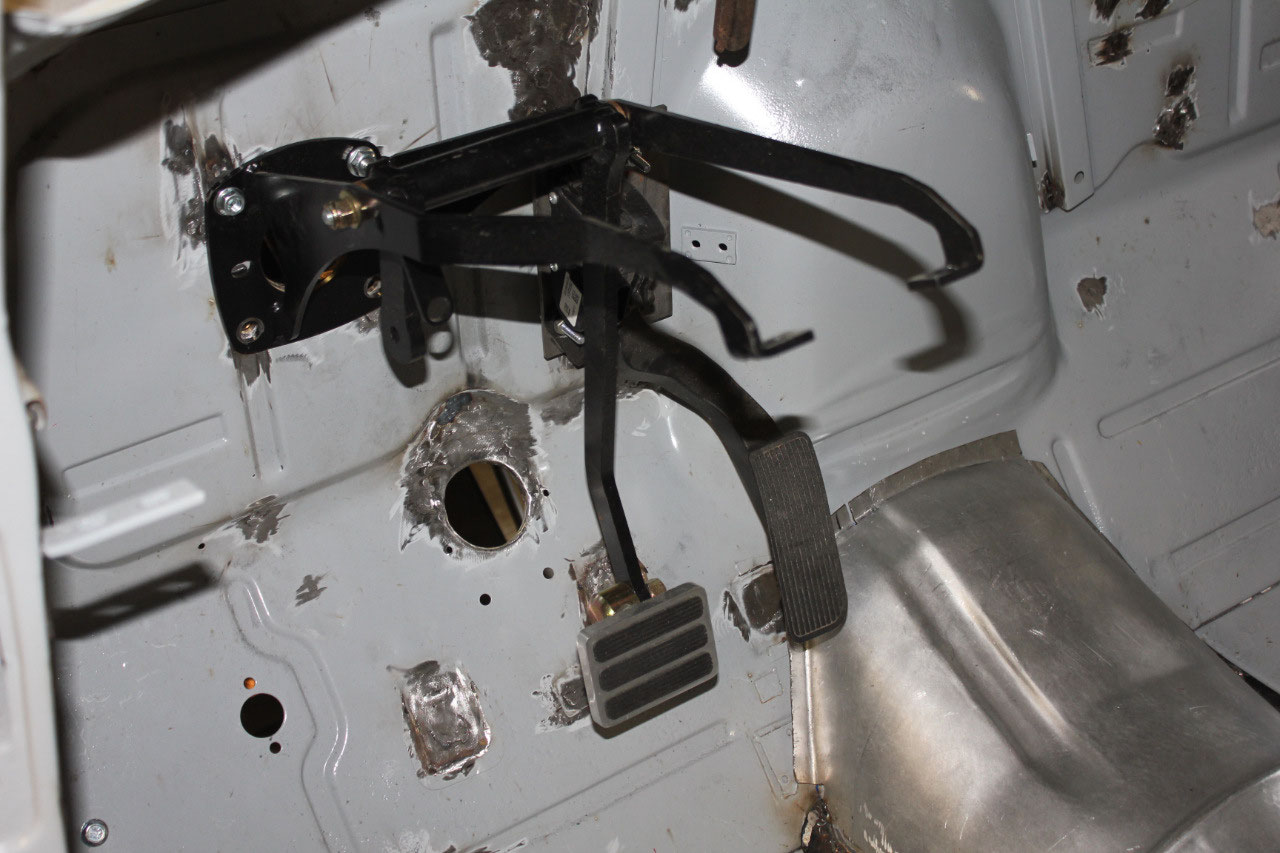
The last section I worked on was the gas pedal. I had originally used a leftover 3/16” steel
plate to locate the gas pedal.
It
attached to a vertical brace on the firewall with two bolts that pass through
the firewall. My original plan was to
just weld the plate in place and fill the holes in the firewall, but it turned
out that the actuator for the “Power Cowl Vent” is also supposed to attach to
the same vertical brace. I was concerned
with the strength of the sheet metal with the repetitive motion of the actuator
and decided to leave the bolts in place.
I was able to increase the bolt size to 5/16” and use the upper hole for
the plate as the upper attachment bolt for the actuator. Now here’s where I got a little fancy. I bolted the gas pedal to the plate using the
existing ¼” holes and welded the nuts to the back of the plate. This allows me to easily remove the gas pedal
without removing the plate. I also
welded a 5/16” nut to the back of the plate for the lower actuator mount. This meant I had to drill a 3/4” relief hole
in the vertical brace for the welded nut.
I also beefed up the 5/16” holes through the firewall by welding in a ½”
tubular spacer from the vertical brace to the firewall.
This allows me to fully tighten the plate
attachment bolts without crushing the vertical brace sheet metal. It all worked out great! The bolts protrude through the firewall
behind the engine and will be barely visible.
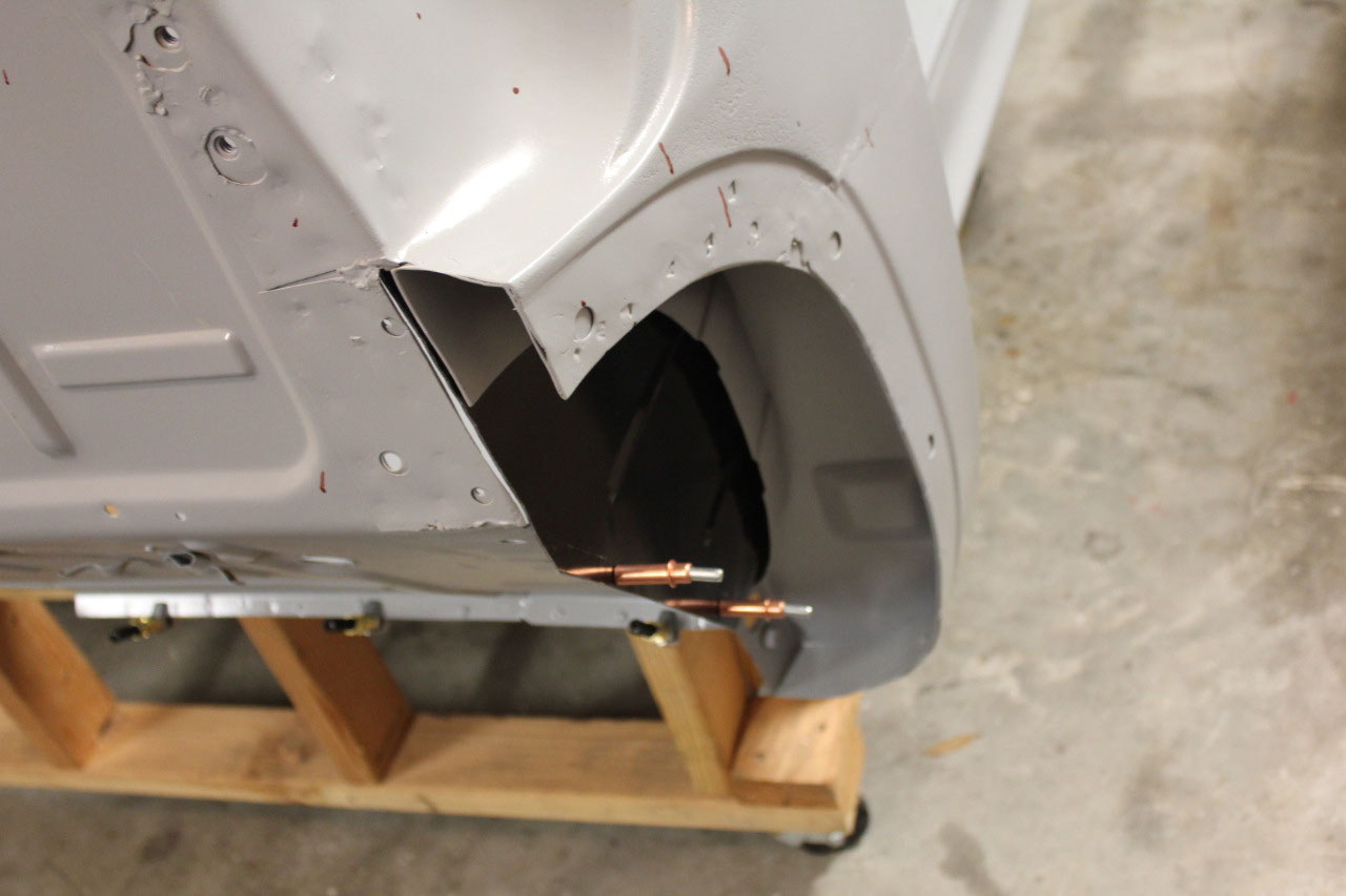
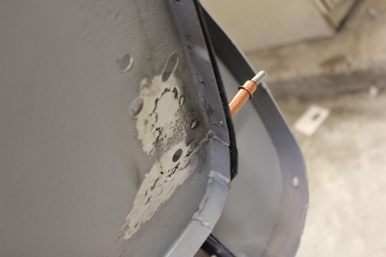
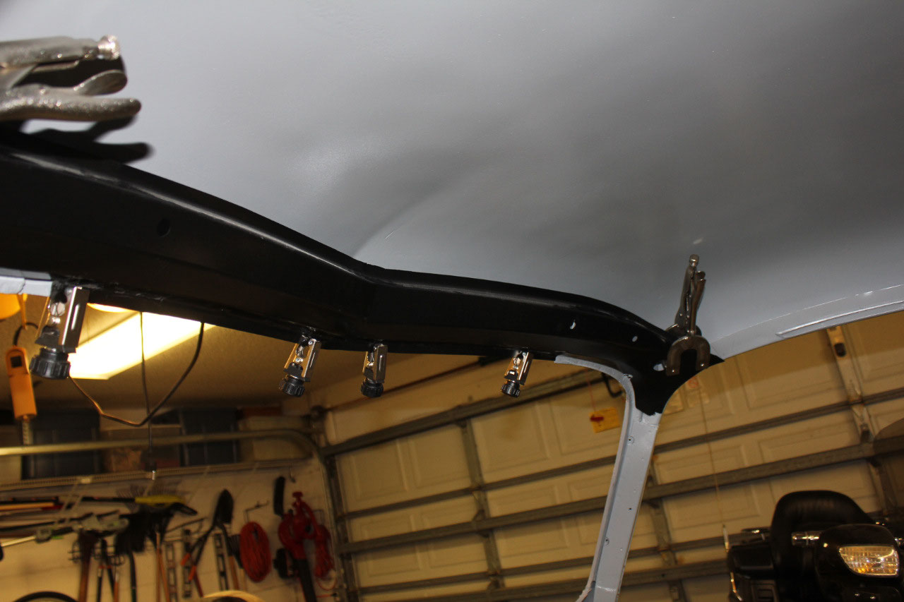
I also began test fitting the front upper roof brace. There was evidently some rust on this piece
originally due to a leak in the upper part of the windshield. The previous owner did some repair on the
upper windshield channel and it all looks like it will fit correctly. I just need to make sure there are no
pinholes in the replacement panel welding before I plug weld the brace in
place. I also need to make sure the
windshield opening is correct. The
Factory Assembly Manual appears to call for a dimension of 15-1/8”, but the
glass that was taken out appears more like 15-1/4” to 15-1/2”. I’m not sure exactly what the profile of the
windshield rubber looks like, and I’m not sure where the glass fits within the
opening. So I ordered a new windshield
rubber so I can make sure the windshield will fit before I weld it up.
Unfortunately, I can’t weld anything at this time. Soon after I started welding, I ran out of
Argon shielding gas. I refilled the
tank, and after a little advice from my neighbor about increasing the shielding
gas pressure from 10 psi to 20 psi, the welds were looking pretty good. Unfortunately, a couple of days ago, when I
finished for the day, I forgot to turn off the gas. Evidently, it must have leaked down, because
the tank is now empty again. Lesson
learned! We’re getting ready for our
last cruise of the season, our annual anniversary cruise. So for now, I’ll just cleanup the garage,
follow the imminent hurricane Dorian, and wait until we return on the 15th
to get back to work.


2025-05-22