 Orlando, Florida, United States
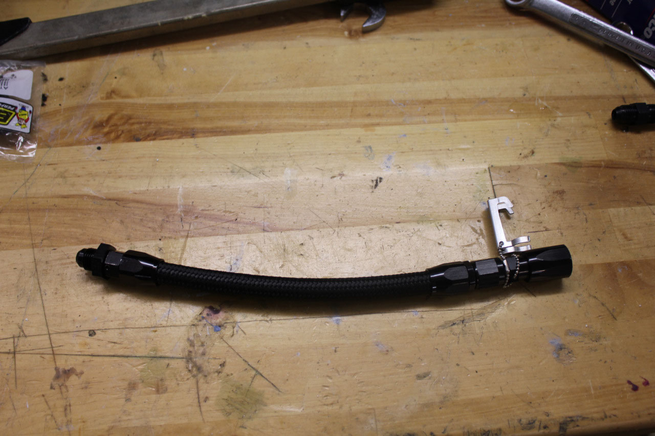
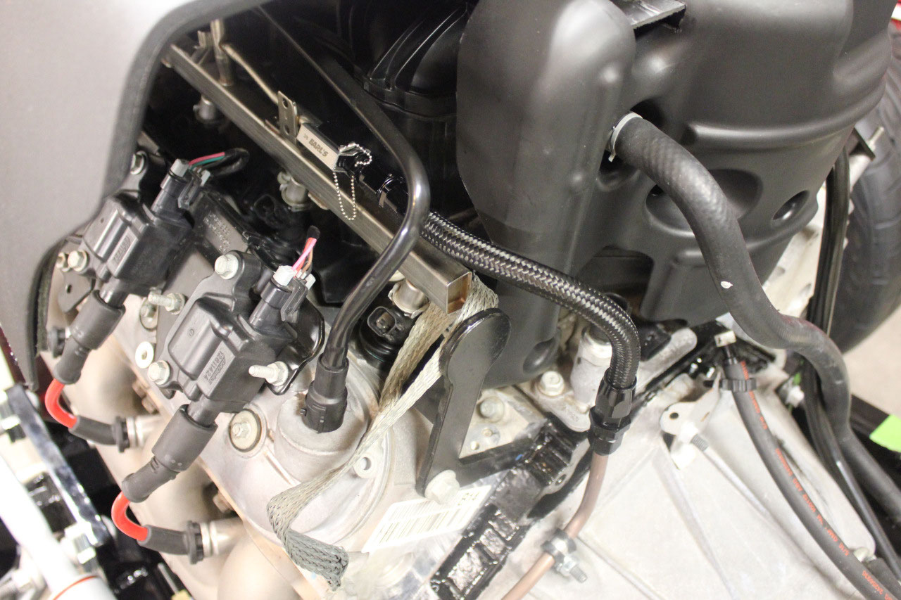
The first project was to make up the flex fuel lines. I stuck with Earl’s Performance products for
the AN fittings and Earl’s Pro-Lite Ultra flex hose. I think its black nylon jacket looks better
than the braided stainless, and should hold up better over time. It was easy to cut and the fittings went on
easily and look very professional.
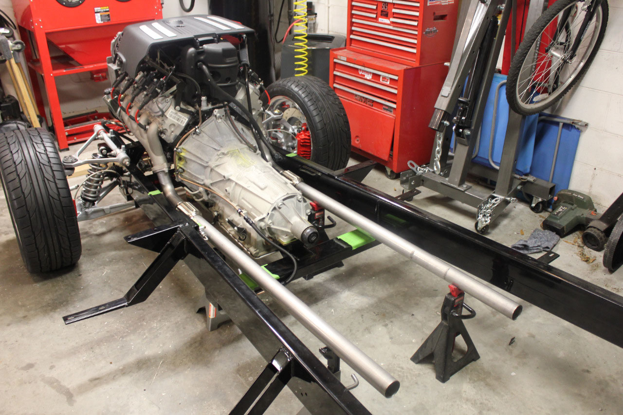
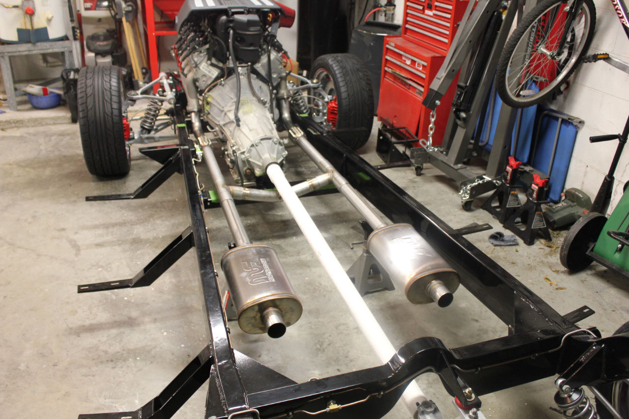
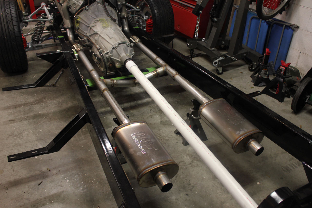
The exhaust parts have come in, and I began the mockup of
the exhaust. It looks pretty good, since
the Hooker exhaust manifolds are 2-1/4, I decided to stick with the 2-1/4 all
the way through. In retrospect, I
probably should have bumped it up to 2-1/2 after I got past the downpipe, but
I’m sure the 2-1/4 will be fine. I am
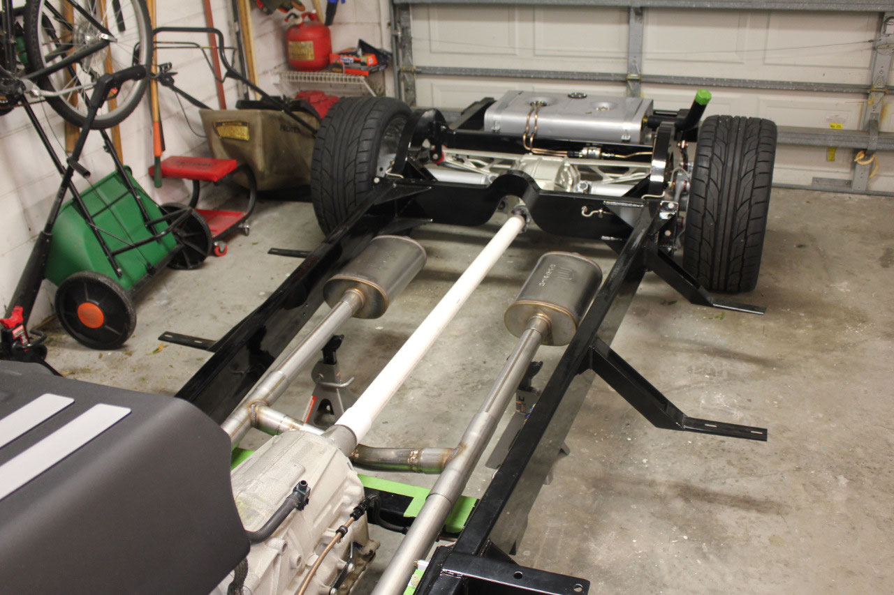
keeping the exhaust system above the transmission crossmember and inside the
frame rails. This should make for a
clean installation and great ground clearance.
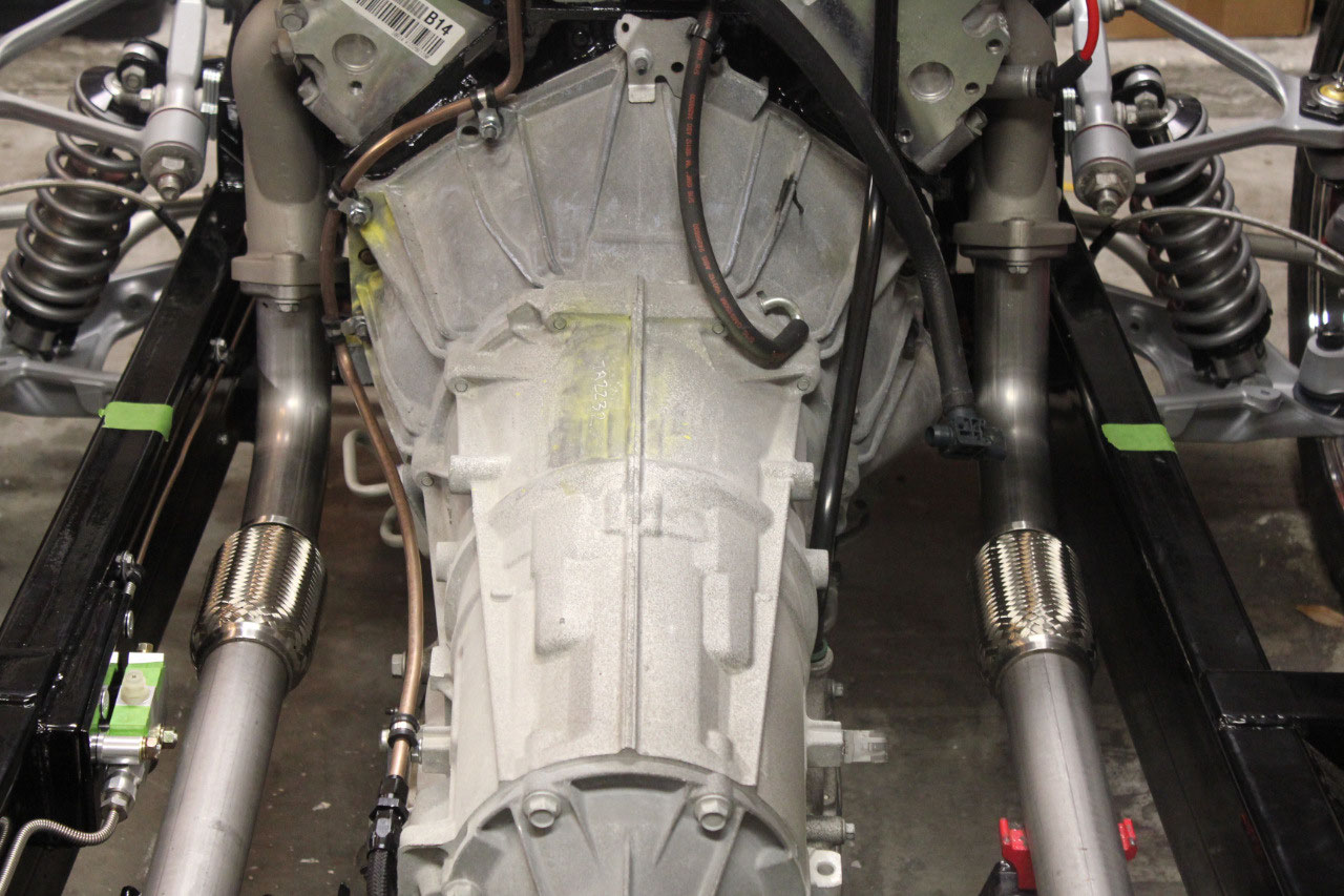
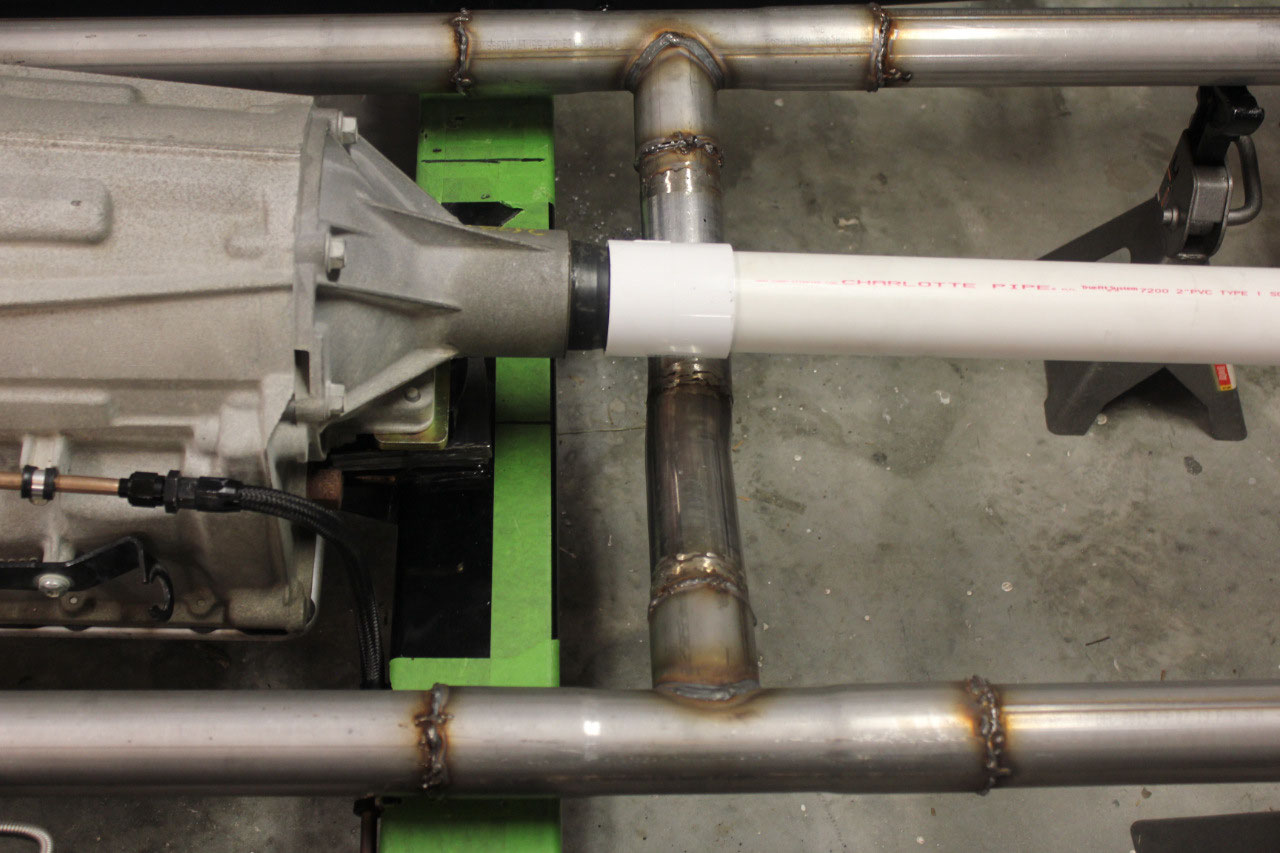
As I began laying out the H-pipe, it became apparent quickly that the
downward V-shape would not go down low enough to give clearance for the front
u-joint. I ended up ordering a pair of
2-1/4 x 15 degree bends.
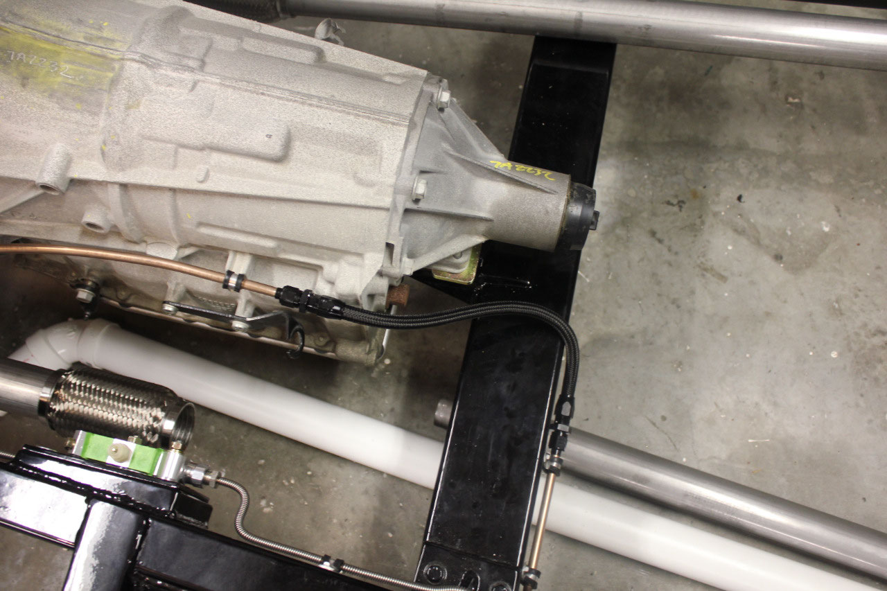
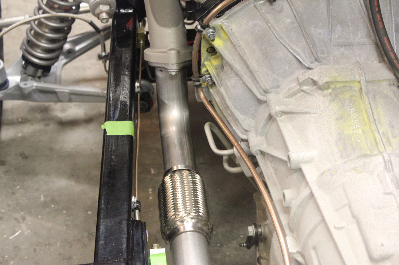
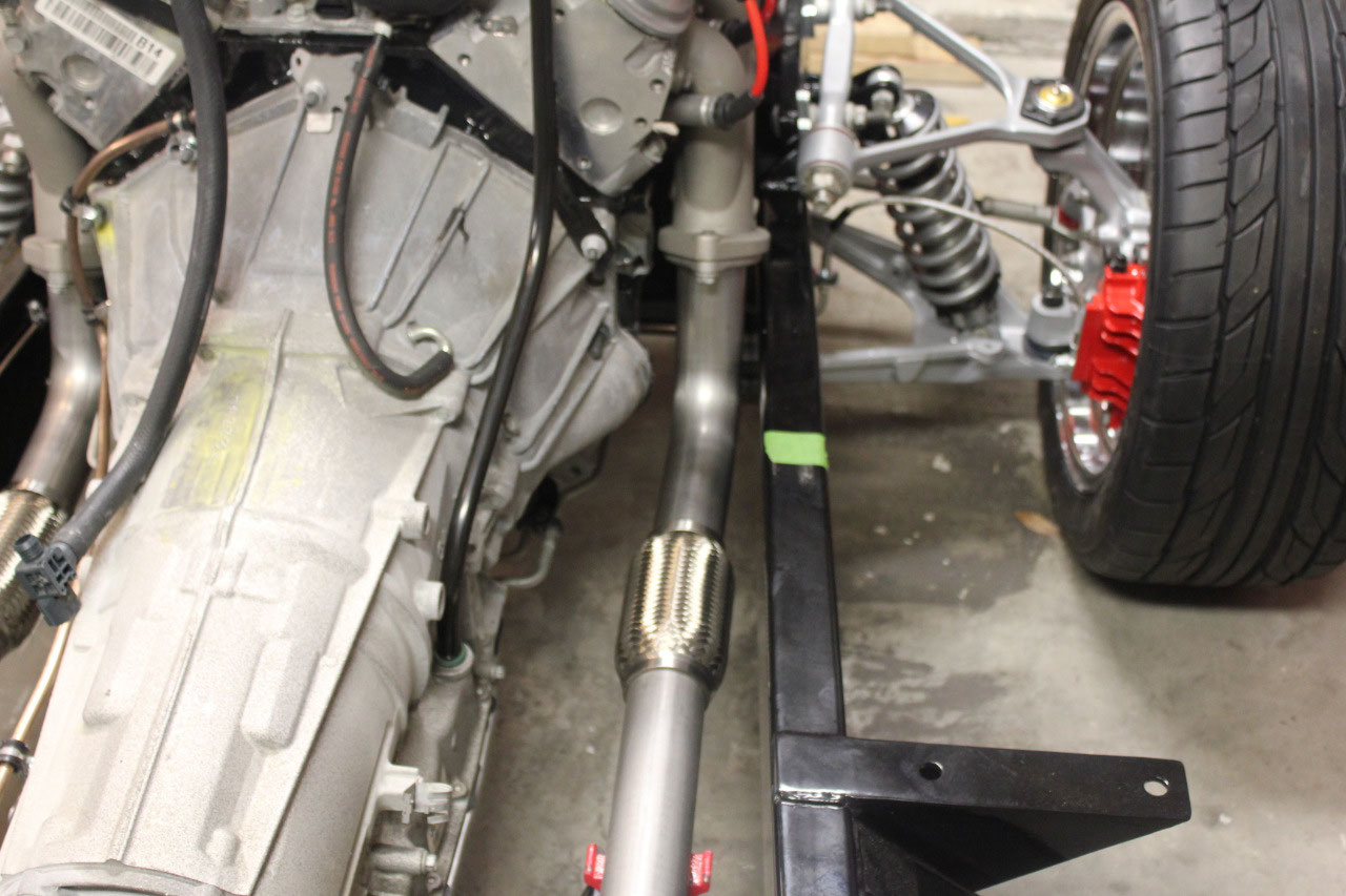
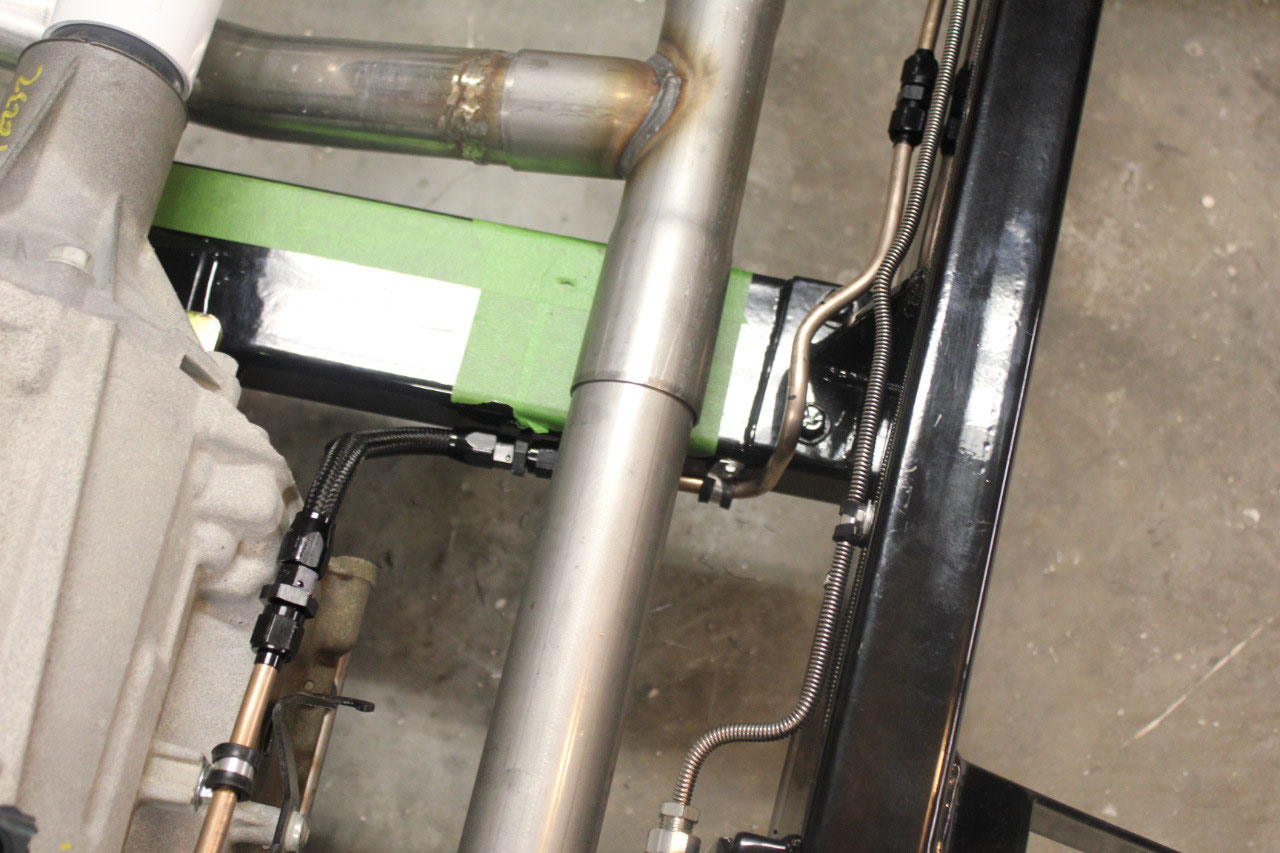
Also, the flex
fuel line on the transmission crossmember is just a little too close to the
exhaust. I was trying to keep the flex
line behind the crossmember for protection from road hazards, but I’m sure it
will be fine on the front of the transmission crossmember. Of course, I needed another 3 foot section of
3/8 cunifer line to remake the fuel line to the front of the crossmember.
The 15 degree bends finally came in, and when I mocked it
up, it all looked great! Looks like
plenty of clearance for the front u-joint, and the V-shape doesn’t drop below
the transmission crossmember. Now it’s
time to see how well I can stainless weld.
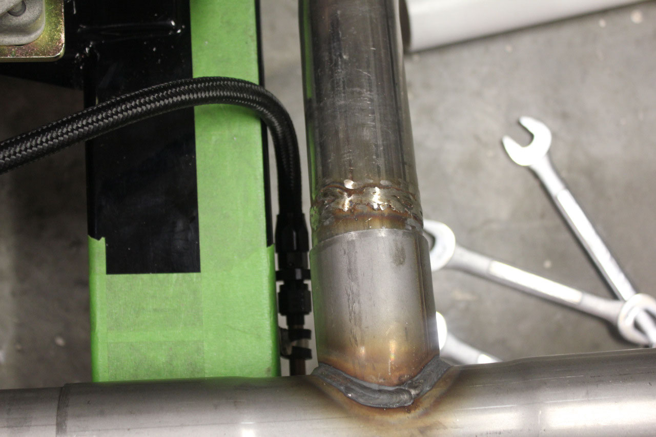
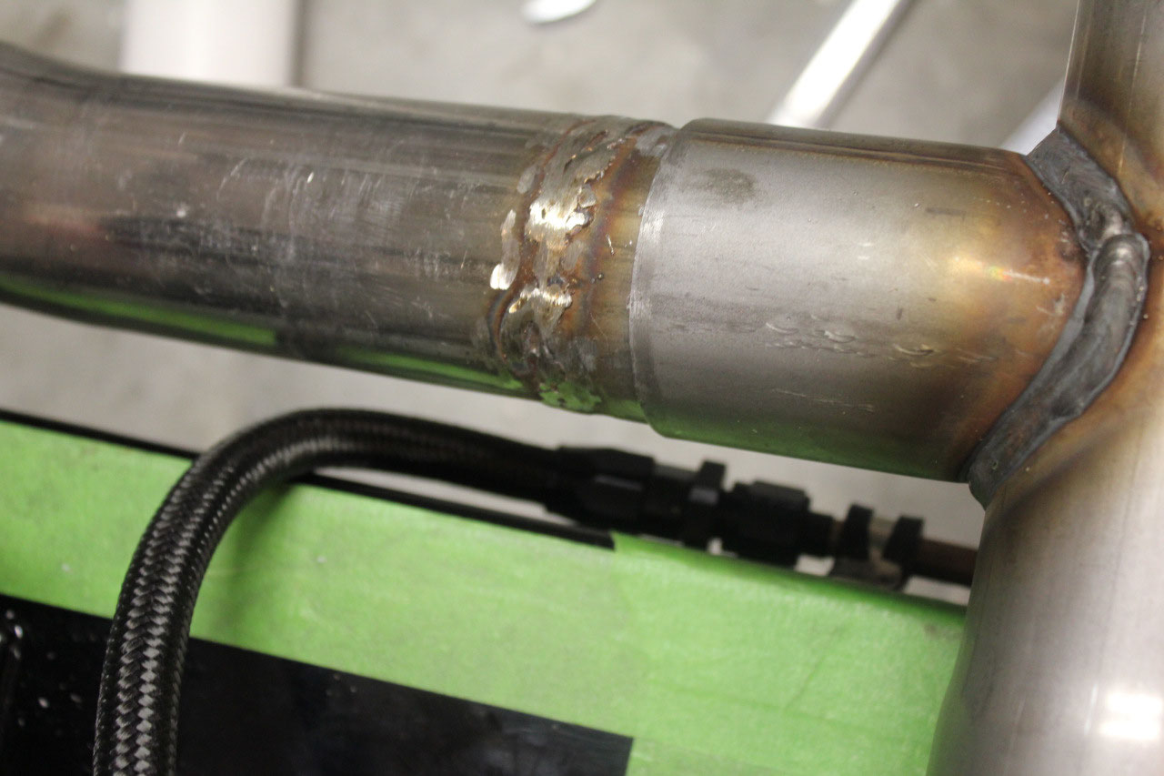
The 15 degree bends are the most difficult as the pipes are just butt
welded. I just took it slow, tack welded
everything in place on the truck and pulled the entire exhaust out to complete
the welding on the bench. As I welded
each section, I would look inside the pipe to be sure I had penetration completely
around the pipe. The welds came out
good, not quite as pretty as I would like, but not bad for an amateur welder.
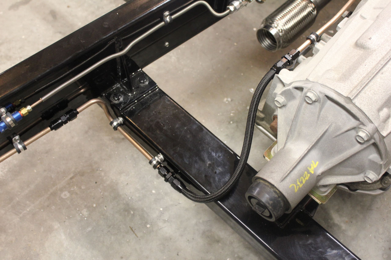
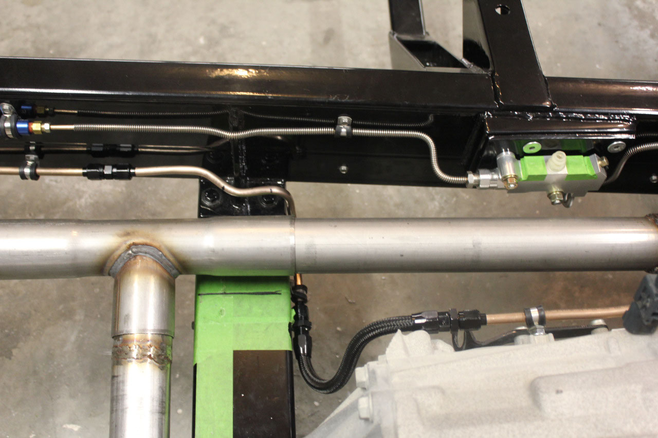
The cunifer pipe for the fuel line came in, and it was easy
by now to make up a new line to the front of the transmission crossmember and I
was able to take apart the flex line, shorten it and reinstall the
fitting. The fuel line is now done and
looks much better with plenty of clearance.
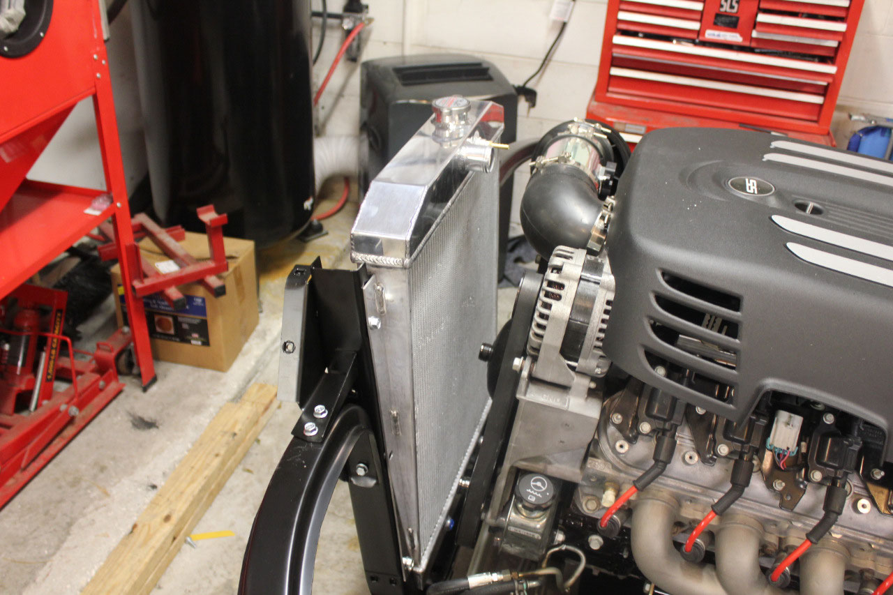
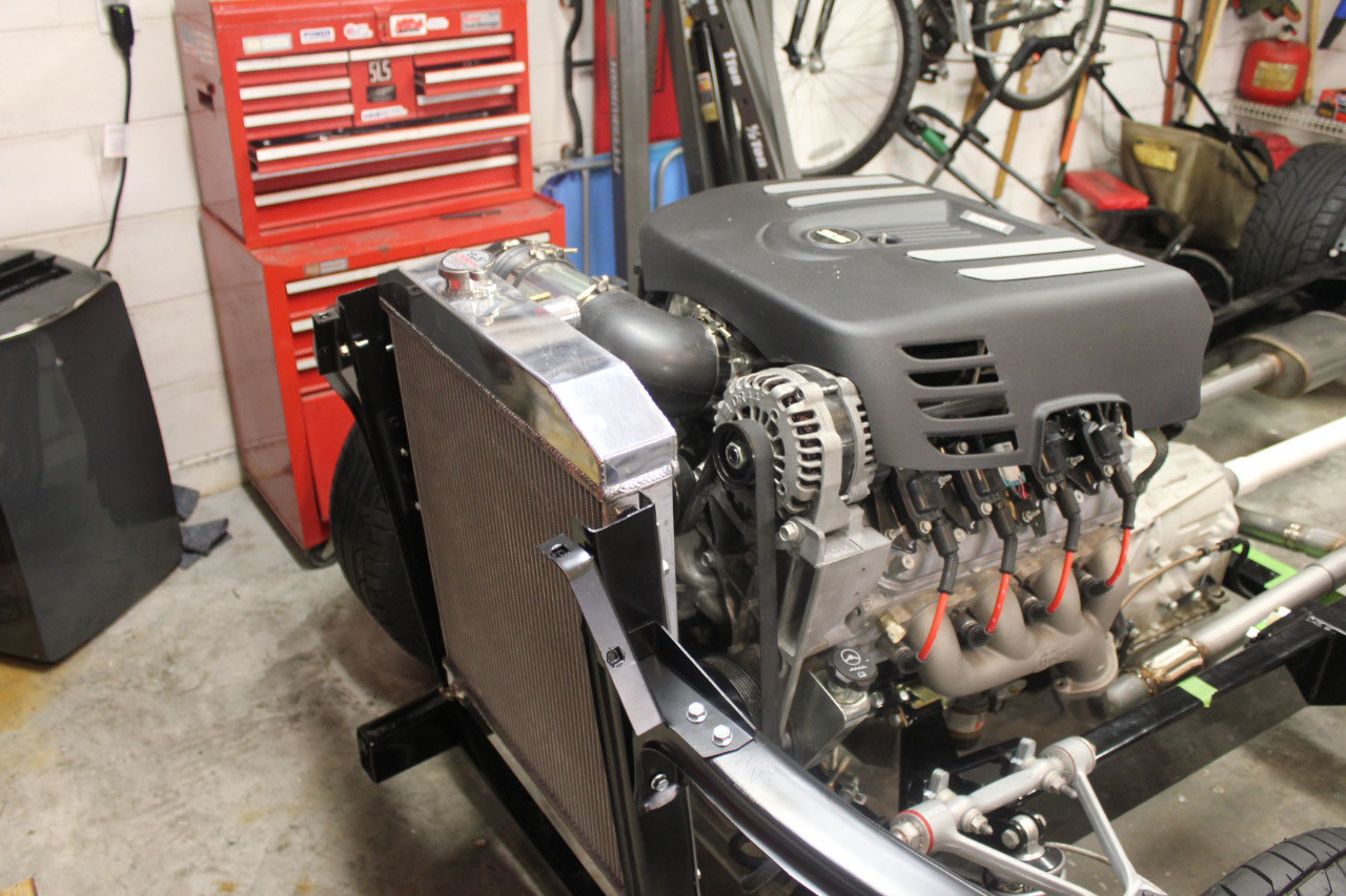
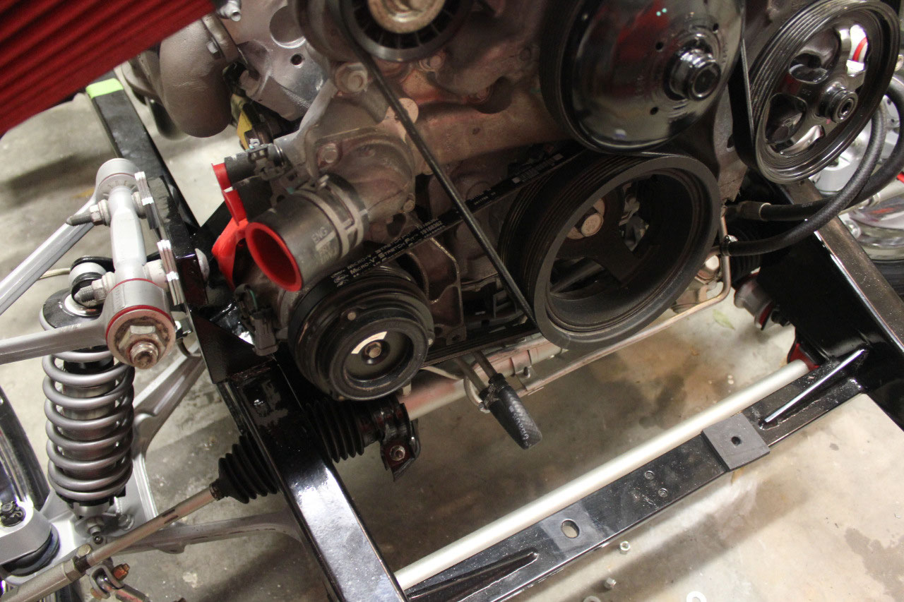
It’s all looking good, but the more I look, the more I am concerned with
clearance from the front of the engine to the radiator. I know there is room, but I am concerned that
there may not be room for an electric fan.
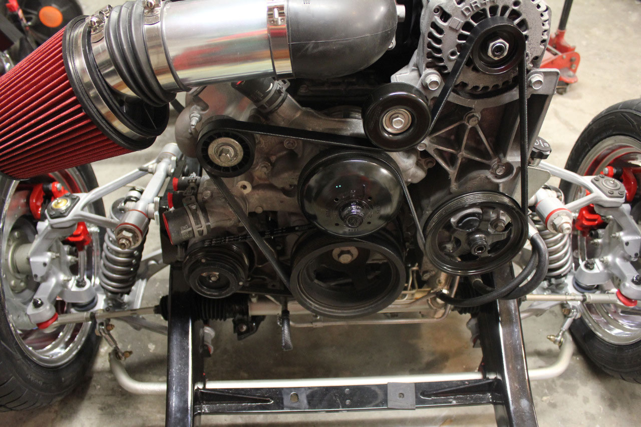
It also looks like there is plenty of firewall clearance, and the engine
should really be moved back about 1 to 1-1/2 inches. I’m sure it would be fine with a regular
small-block Chevy, but the Vortec truck engine is a bit long around the
accessories and I really want to keep the stock truck accessory configuration.
Rather than holding off until I got a body and a radiator
core support, I decided it was worth the expense and the peace of mind that
would come by spending the $200 for a new radiator core support.
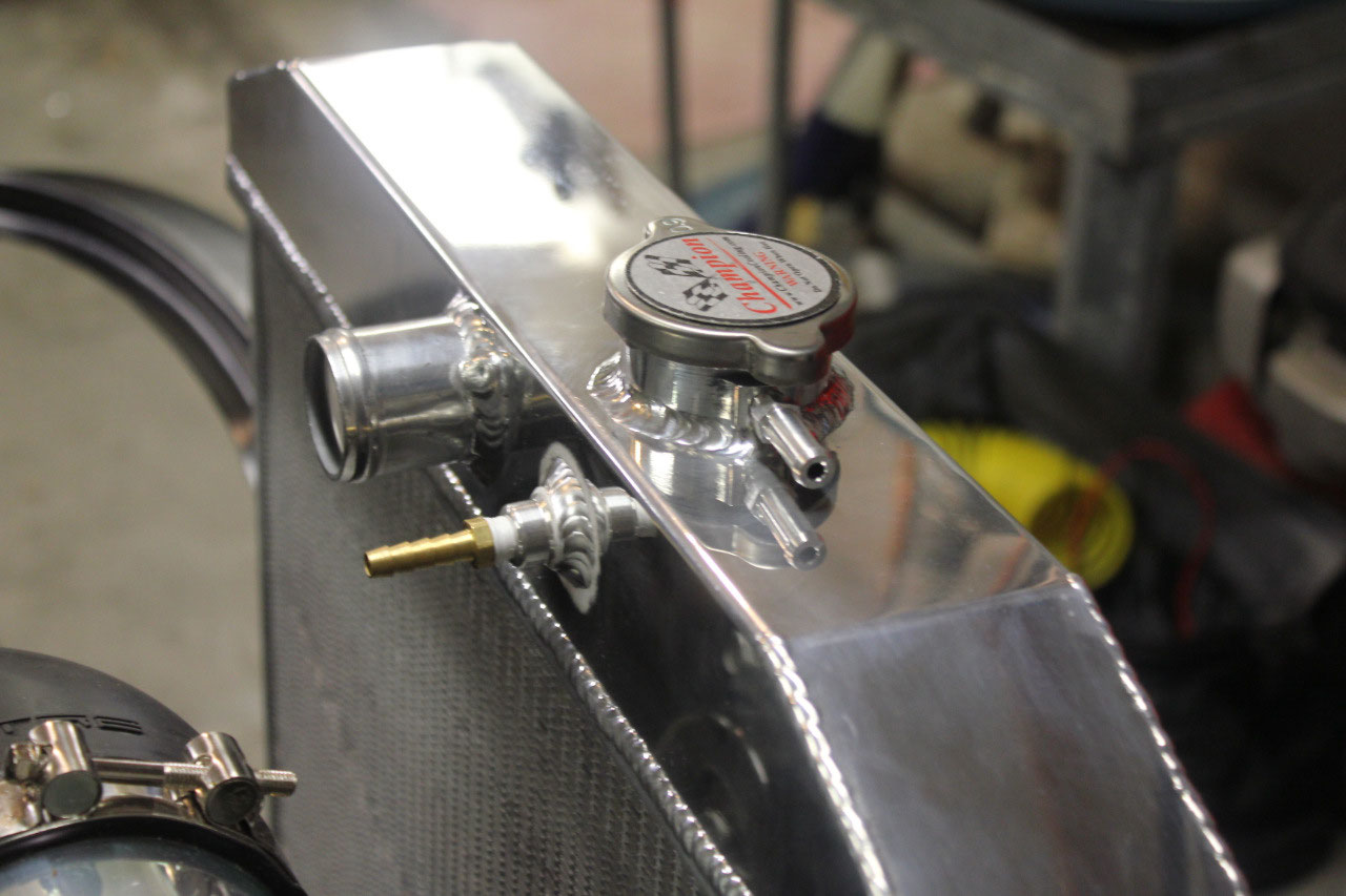
So I ordered the core support along with a
Champion radiator, shroud, and 16” Spal puller fan. When the parts came in, I quickly found out
that the radiator and core support fit fine, but sure enough, there was not
room for the fan and shroud.
In looking at the clearances around the engine, and the
transmission crossmember, it looks like I have room to move back about 1-1/2
inches. For the front, CPP makes an LS
engine mount that looks perfect. The AC
compressor will clear the motor mount, though the AC mounting bracket will
probably need to be trimmed. As for the
transmission crossmember, I will need to trim the crossmember where the mount
attaches as it will hit the transmission oil pan if I slide it back. I thought about all different ways to attach
the transmission mount, but the cleanest was just to make up an adapter plate.
The LS mounts came in from CPP, (nice product, but CPP is
always slow to deliver) and sure enough, the driver’s side fit perfectly and I
did need to trim the AC mount bracket.
Fortunately the AC mount is a cast aluminum piece and the trimming was
easy. I did end up removing the entire
engine/ transmission to install the motor mounts, and I also had to add a ¼
inch spacer on each motor mount to make the mount thickness identical to the
previous adjustable mount. I trimmed the
front of the transmission mount so there would be room to install the crossmember
and jacked up the transmission to see how thick the adapter plate should be.
I was always concerned that the original engine angle was
about 5 degrees, and decided that since I was making up a plate, I should
adjust the thickness to make the angle more like 3 degrees. A ¾ inch thick plate would be perfect. So I ended up using 3 identical pieces of ¼
inch steel. I ended up using grade 8
flat head bolts and chamfered holes to bolt to the existing transmission mount,
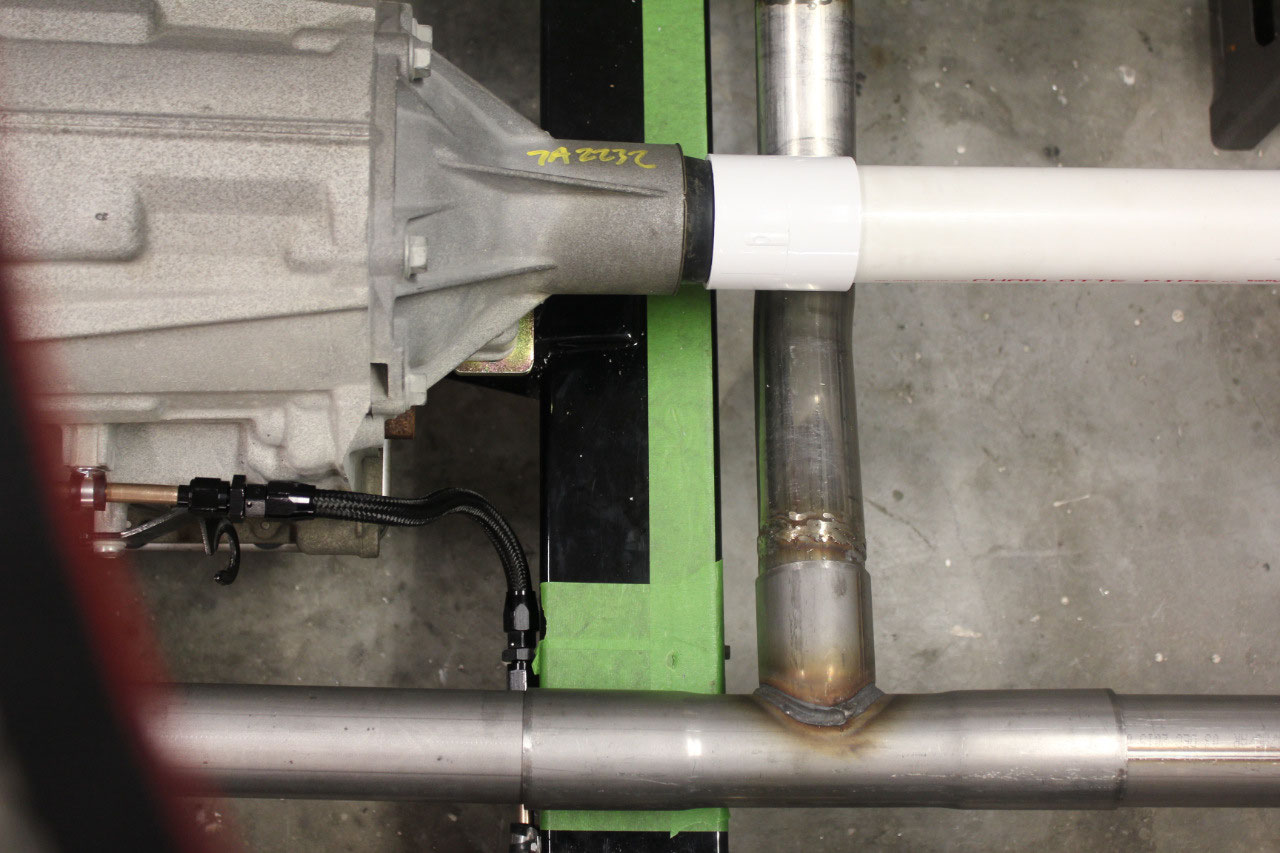
and grade 8 hex bolts to attach to the transmission crossmember. While waiting for the bolts to show up from
McMaster-Carr I went ahead and welded up the O2 sensor bungs and picked up a
piece of 2” PVC pipe to mock up the drive shaft. It’s all looking good, and it looks like the
fan is going to fit, but I will need to cheat it up a little from center to
make room for the water pump pulley.

2025-05-22