 Orlando, Florida, United States
I’m still waiting for the TCM to come back from PSI
Conversions, but the status on their website has changed to shipped, so it
should be here in a couple of days. I
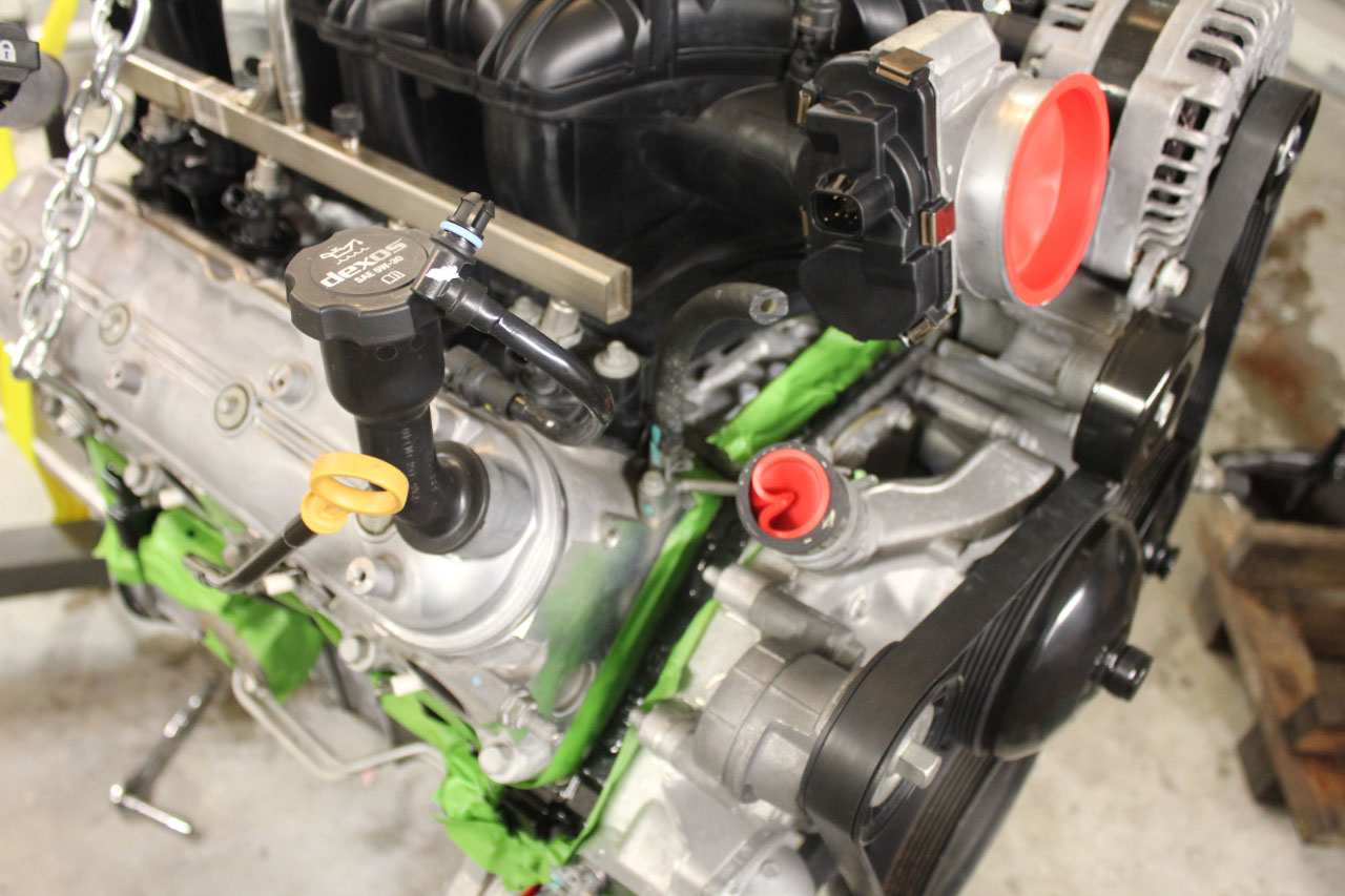
cleaned up most of the engine and it came out well, but the cast iron part of
the block needs repainting. The heads
and most of the accessory brackets are aluminum, so I’m just going to leave
them natural. I got some POR15 Black
Engine paint, and some POR15 prep, but when they came in, the instructions
called for a POR15 Primer, so I ordered the gray and it came in a couple of
days later.
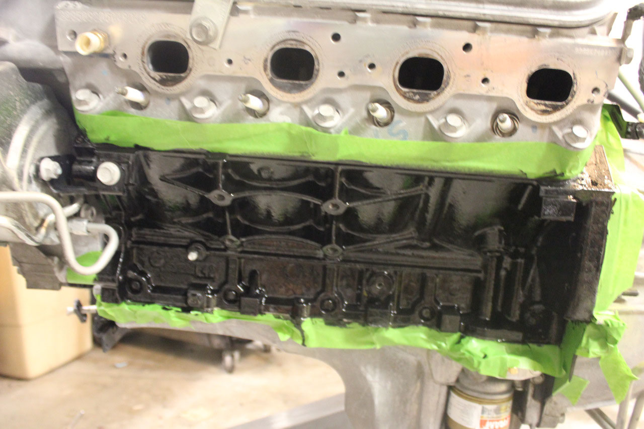
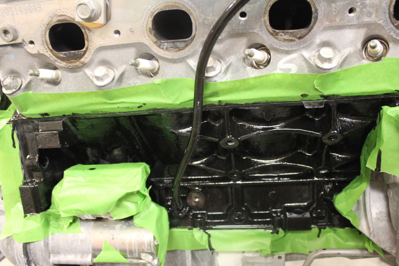
I cleaned all the loose rust off the block with a Dremel and
wire brush, sprayed the prep and primed with the gray primer. When it had dried, I painted the black engine
paint. All of this was done with a brush
as there were just too many nooks and crannies and it would have been too
difficult to mask for spray paint. It
didn’t take much paint at all, and the POR15 Engine Paint flows very well, so
there were no visible brush marks. It
all looks great, and I’m ready when the TCM comes in.
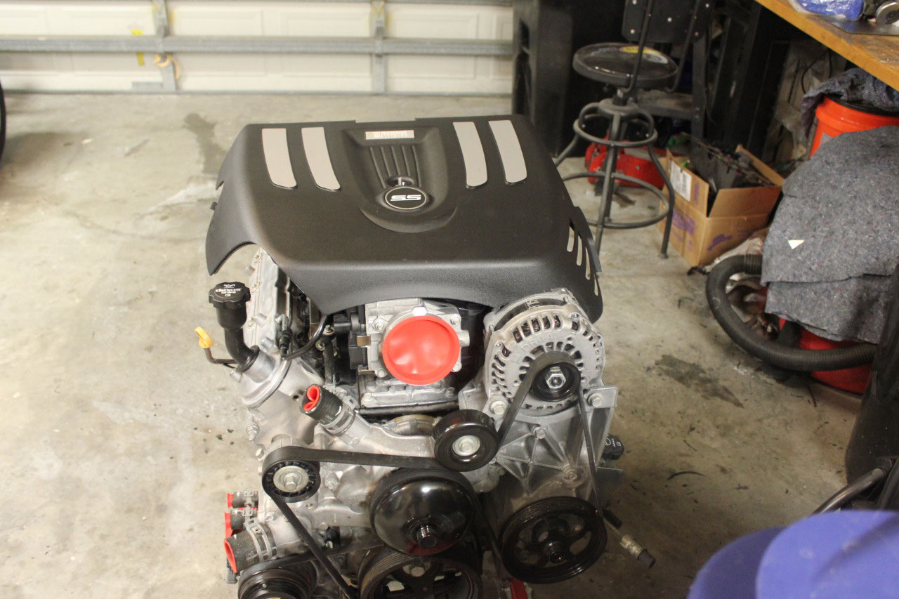
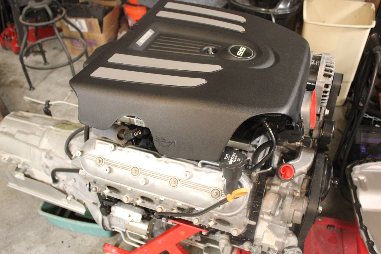
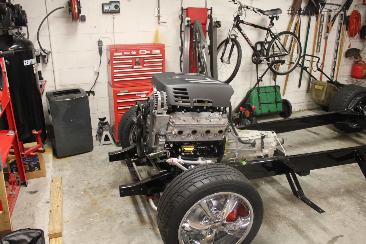
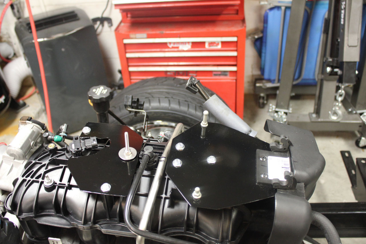
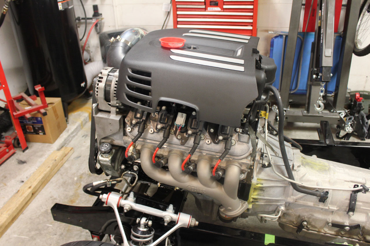
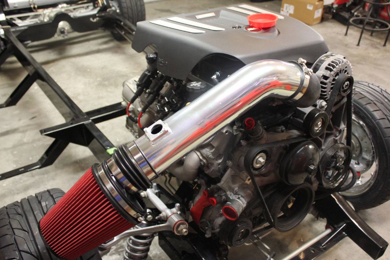
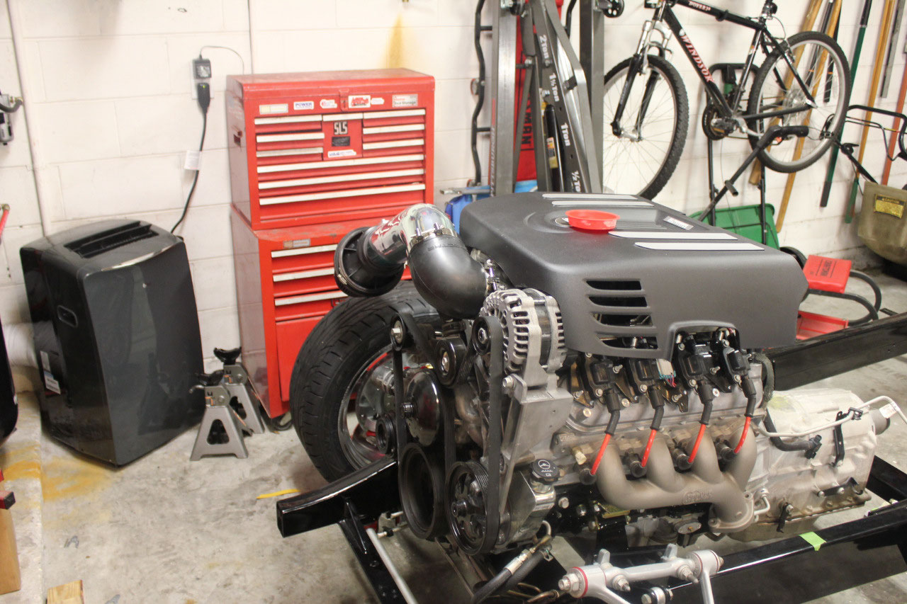
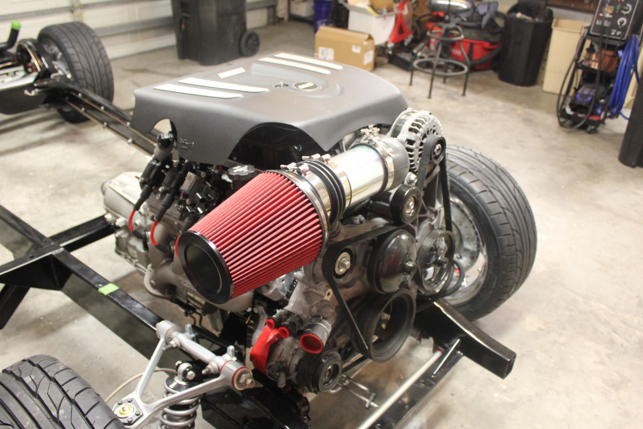
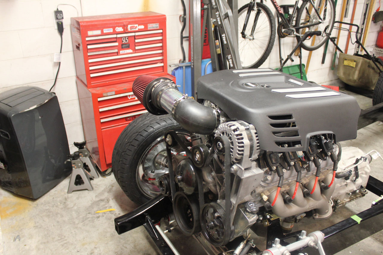
The engine cover came in today, I found this online looking
at a bunch of engines. It’s the factory
cover for a 2006 Trailblazer SS (GM 12600390) and looks about the best that I
have seen. It covers a larger portion of
the engine, most of the coil packs, and has some nice silver stripes and an SS
emblem. Best thing is that it’s only
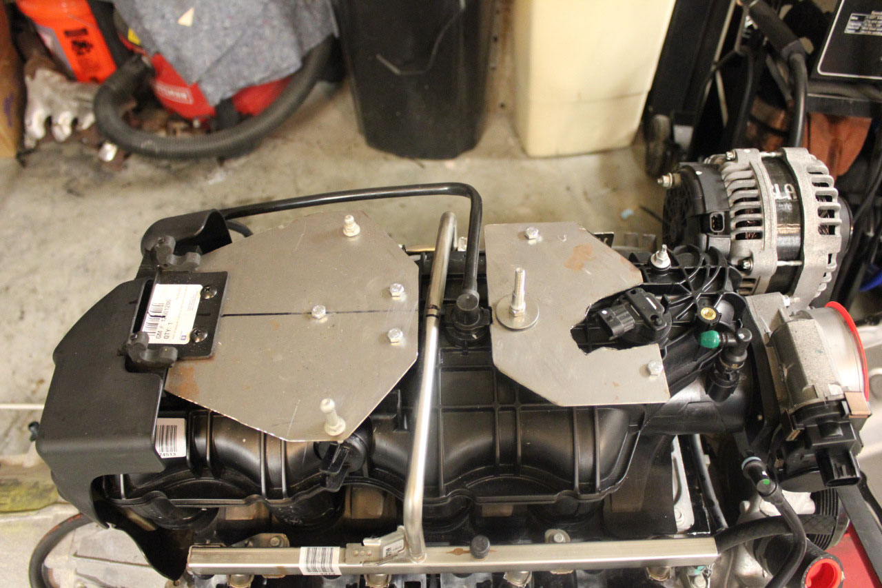
$72. There’s also a mounting bracket (GM
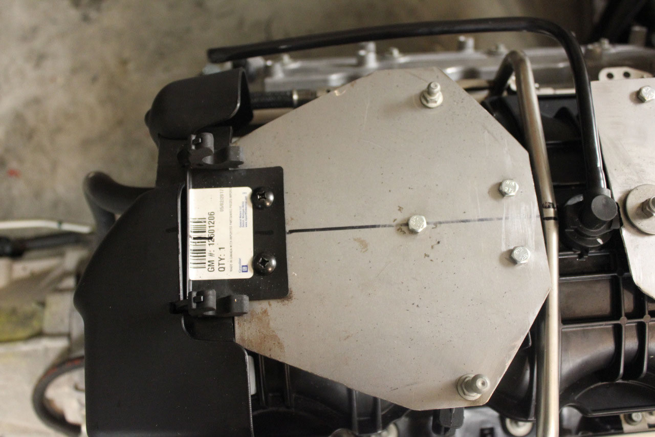
12601206) that fits the cover but not the intake manifold. There are several threaded mounting points on
the Vortec intake, so I just bought a piece of sheet metal at Home Depot, and
fabricated a couple of brackets. They
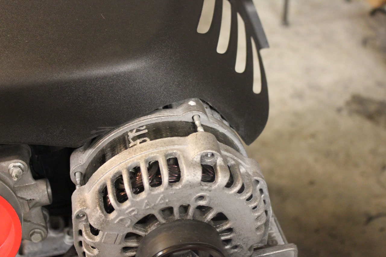
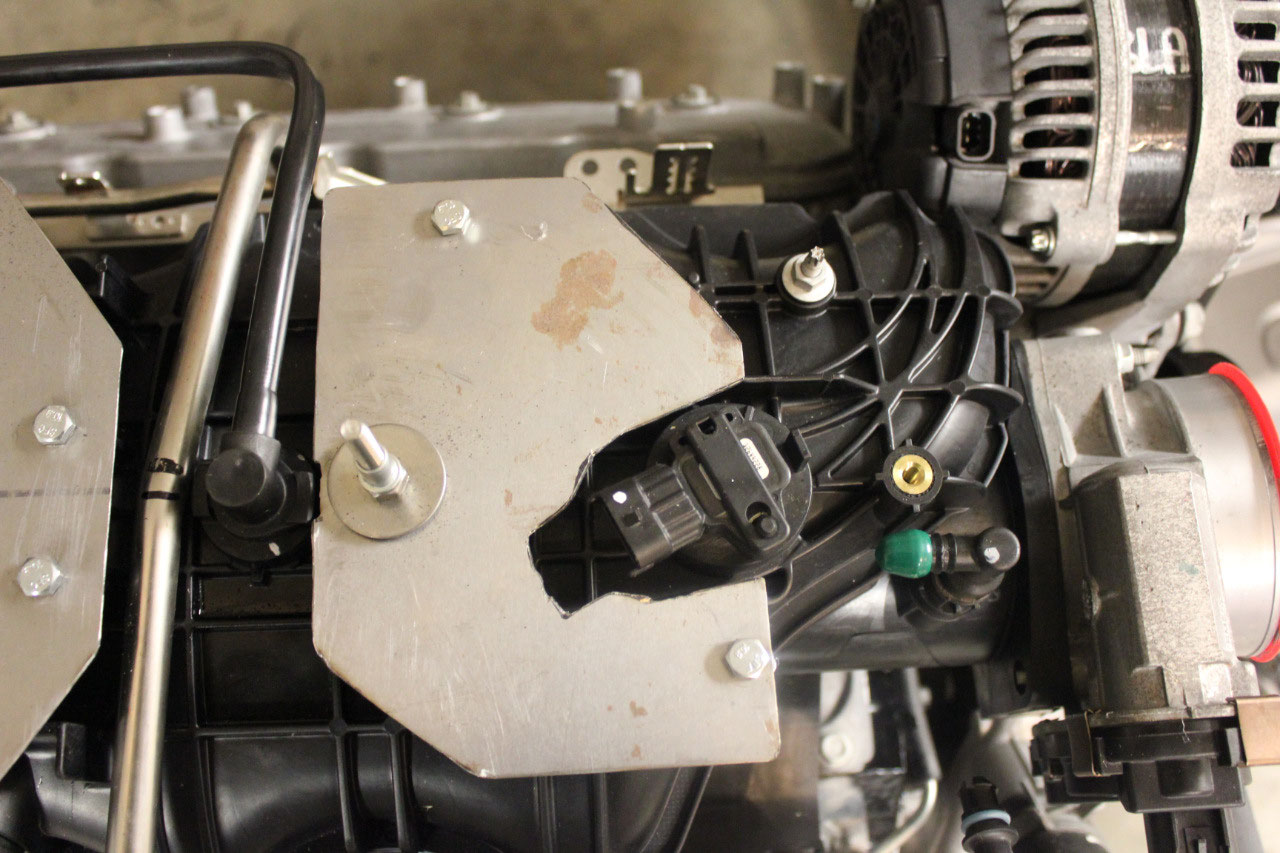
came out great, and the cover is mounted with plenty of rigidity. I had to do a little trimming around the
alternator, and it all fits perfect now.
The TCM and harness came in today and the harness looks
great! Very good quality, and it looks
like it will fit fine. The connectors
all look correct, except for the oxygen sensors. This was not unexpected, as the PSI website
warned that all their harnesses use the same O2 sensors. These are the 5-pin Corvette sensors (GM
12581966). They’re only about $52 each,
and they probably should be replaced anyway, so I just ordered a pair of new
ones.
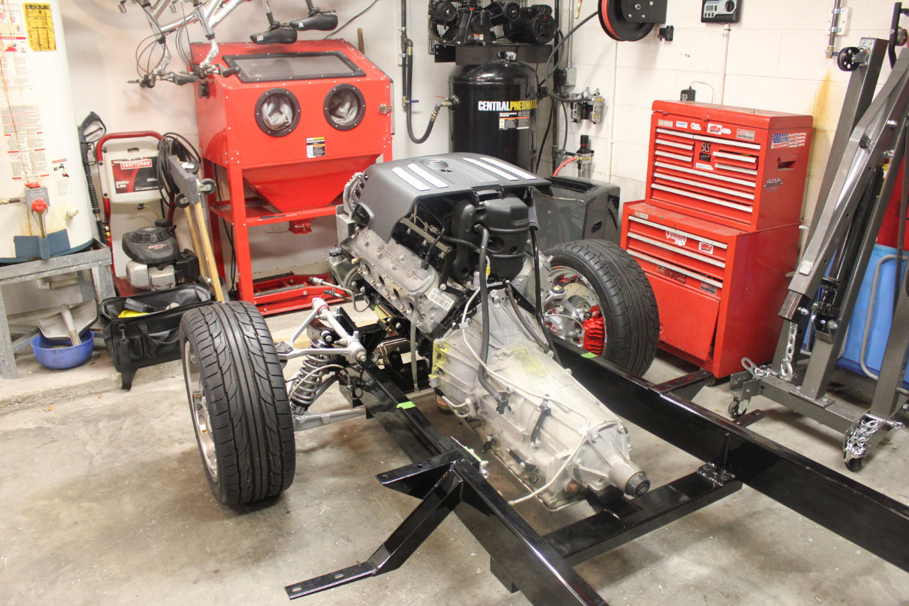
The TCM installed easily, and while I was at it I replaced
the transmission oil filter and pan gasket.
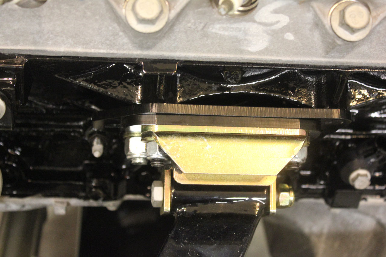
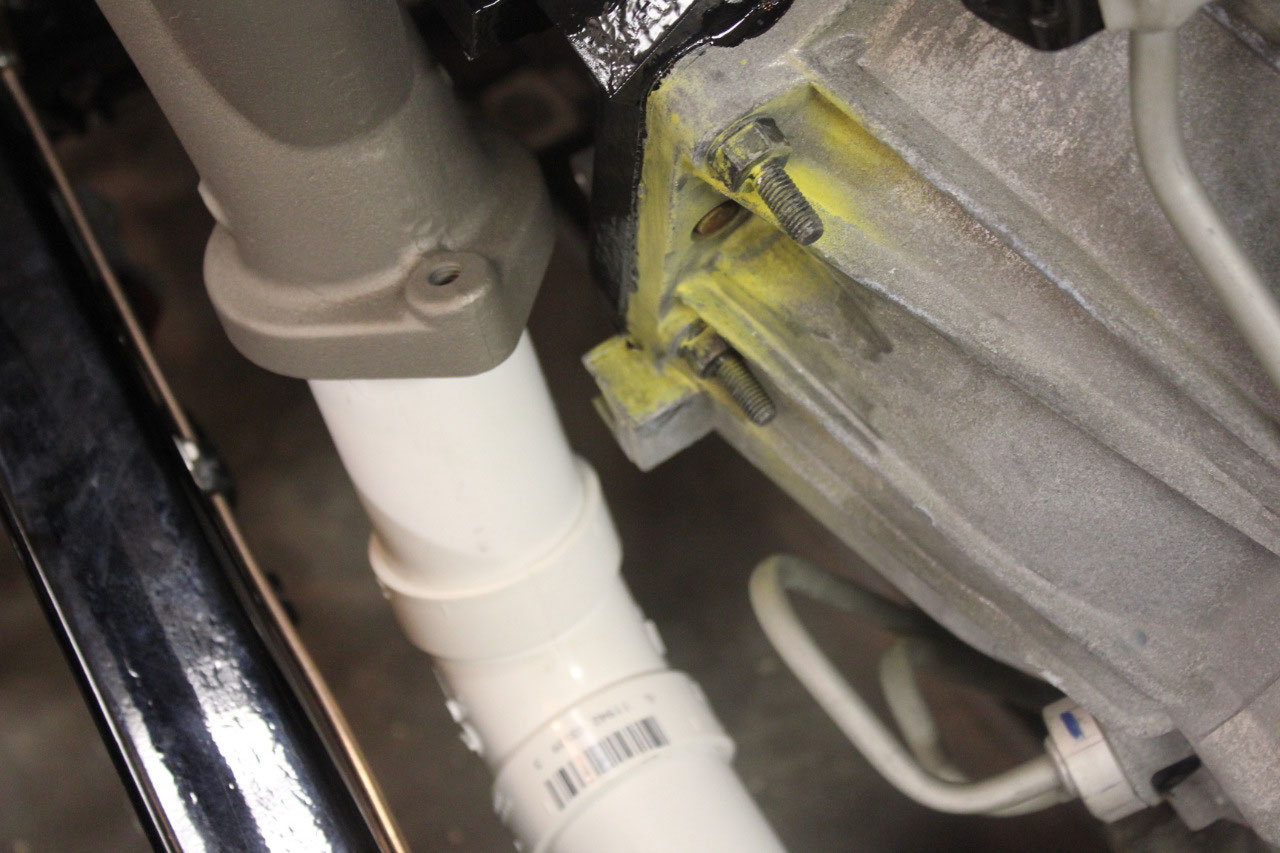
I also had to change the transmission mount as the Tahoe mount was a
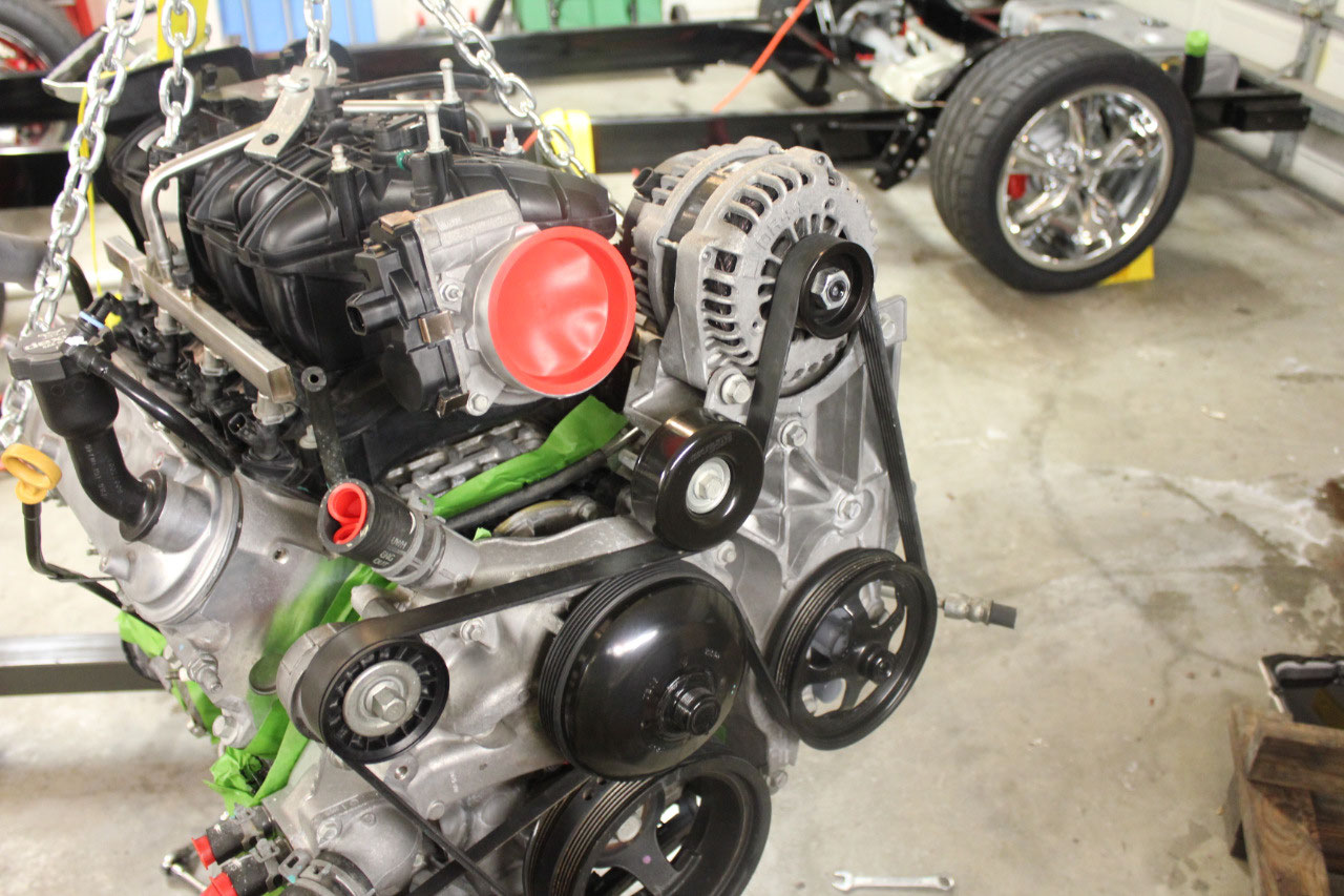
single center bolt and I needed the traditional GM 2-bolt. The engine mounts were the adjustable LS
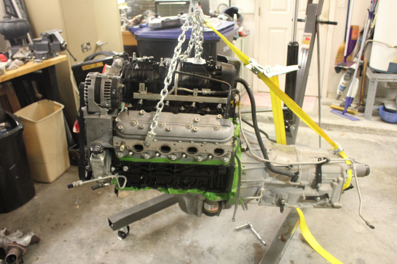
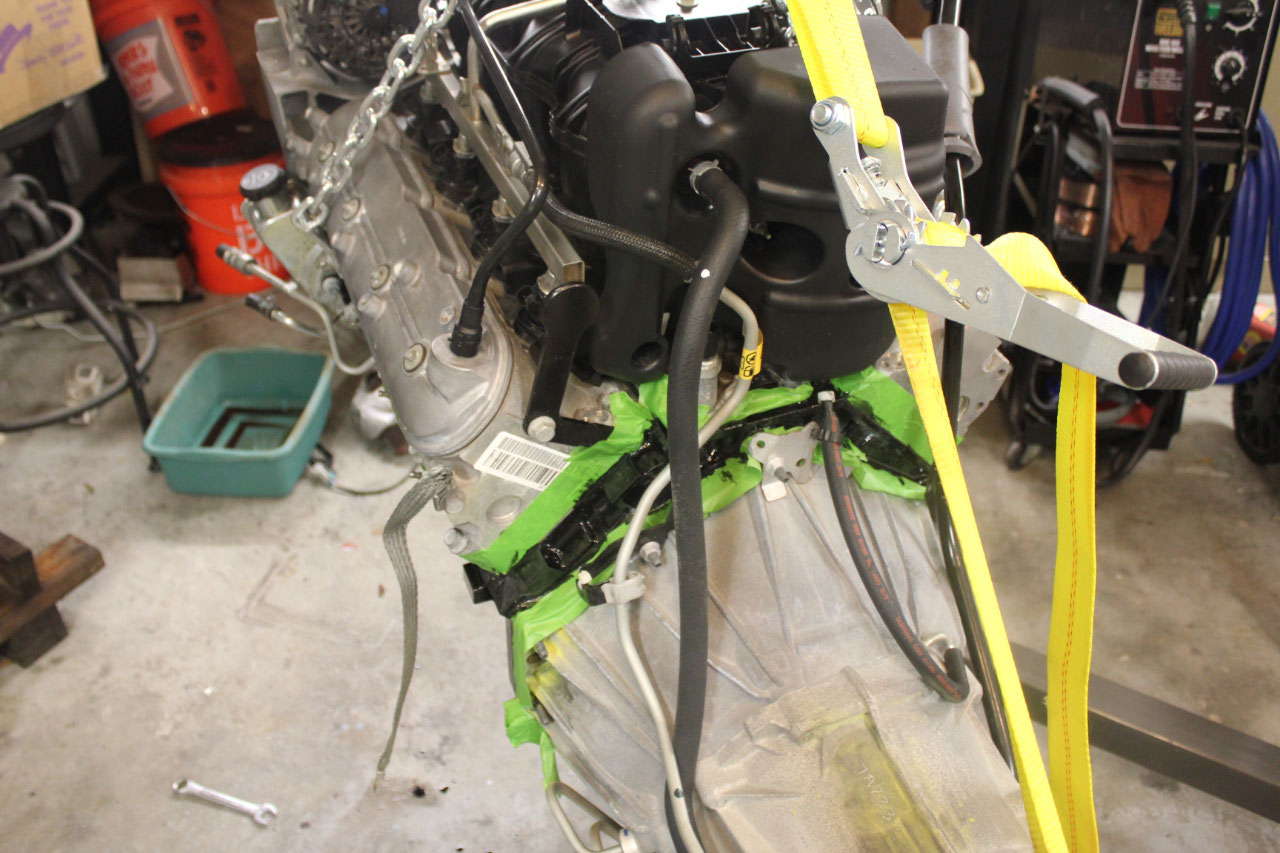
mounts from CPP that Darrell had recommended and they fit perfectly. I lifted the engine from a couple of extra
holes in the side of the head, and ran a strap to the transmission tailshaft to
level the unit. It all looked
great!
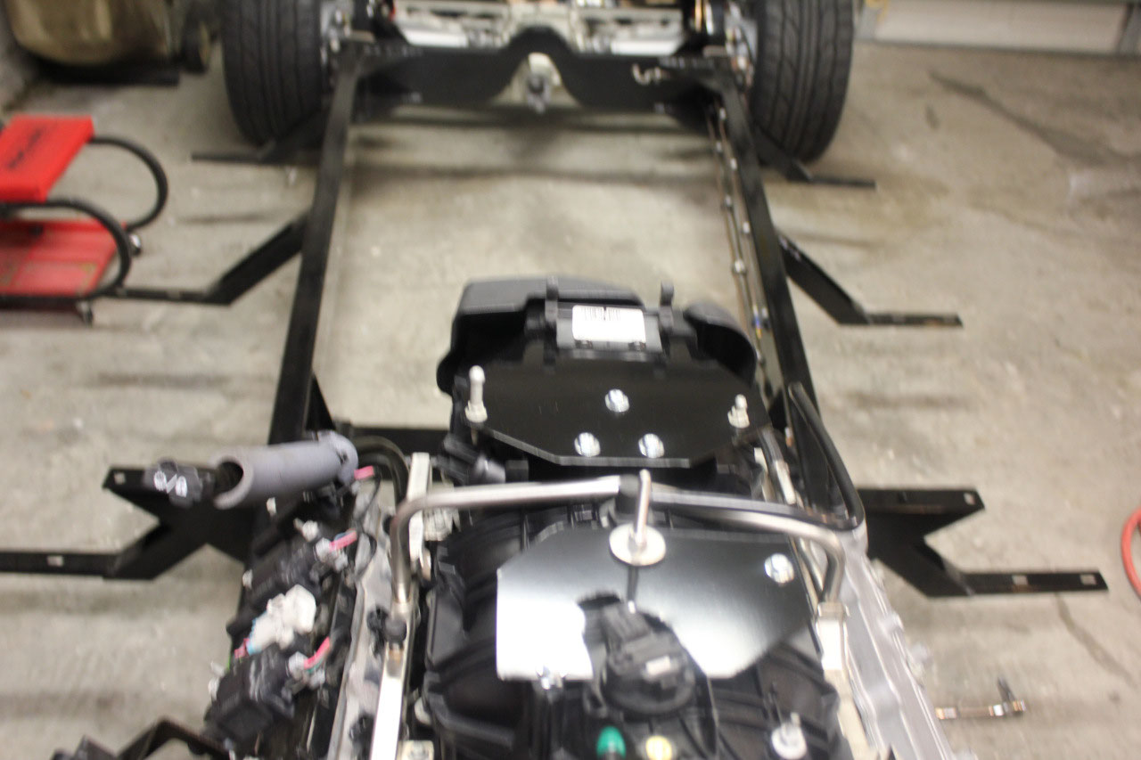
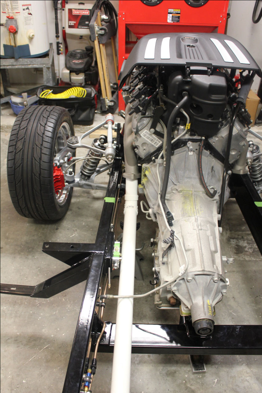
I had planned on installing from the side, but it soon
became obvious it would be better from the front. So I rolled the chassis back, partly outside
the garage and rolled the hoist in from the front. The engine/transmission set down and dropped
right into place. The engine mounts
dropped in perfectly and the bolts lined right up. Even the transmission bolts dropped right
in. There were no interferences
anywhere, and it all looks great!
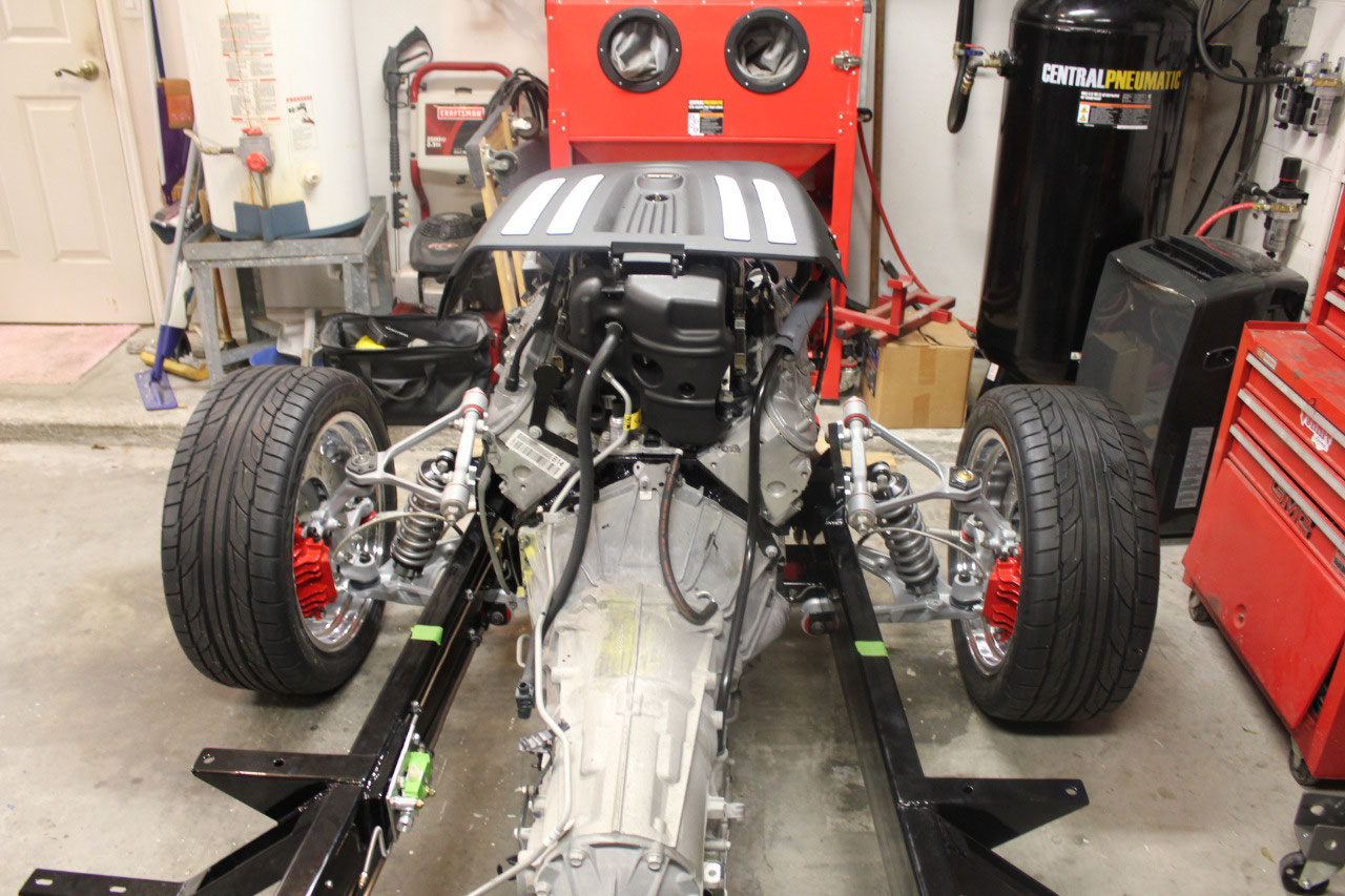
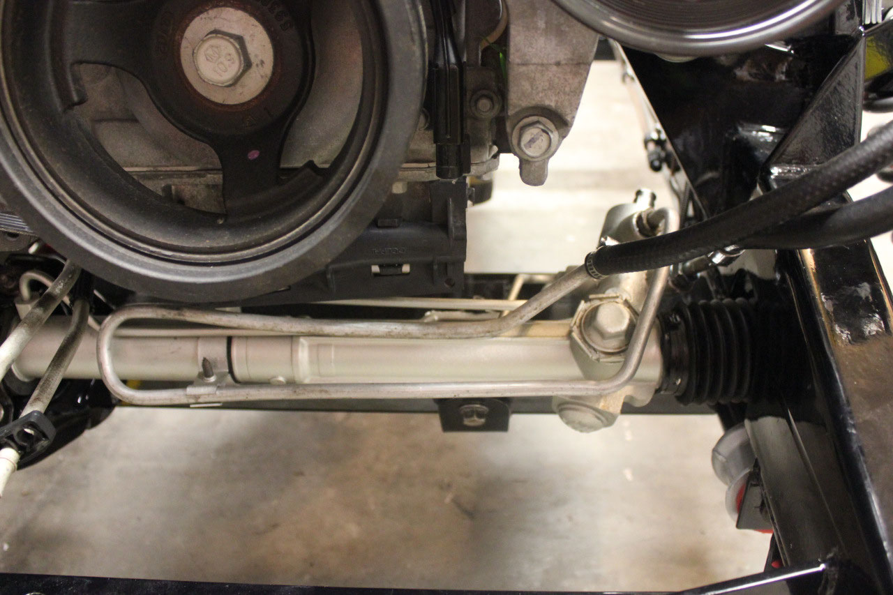
I checked the front/back clearances between the radiator
core support mounts and the tape marks where I expect the firewall to be. The adjustable motor mounts and the
transmission mount slots give about 1.5 to 2 inches of front to back
adjustment. I initially installed
centered, but it was obvious that radiator clearance would be more difficult
than firewall clearance. The radiator
will certainly clear, but I am concerned about room for an electric fan. I moved the adjustment as far back as I can
and I think there is enough room for an electric fan, if not I may need to use
a pusher fan.
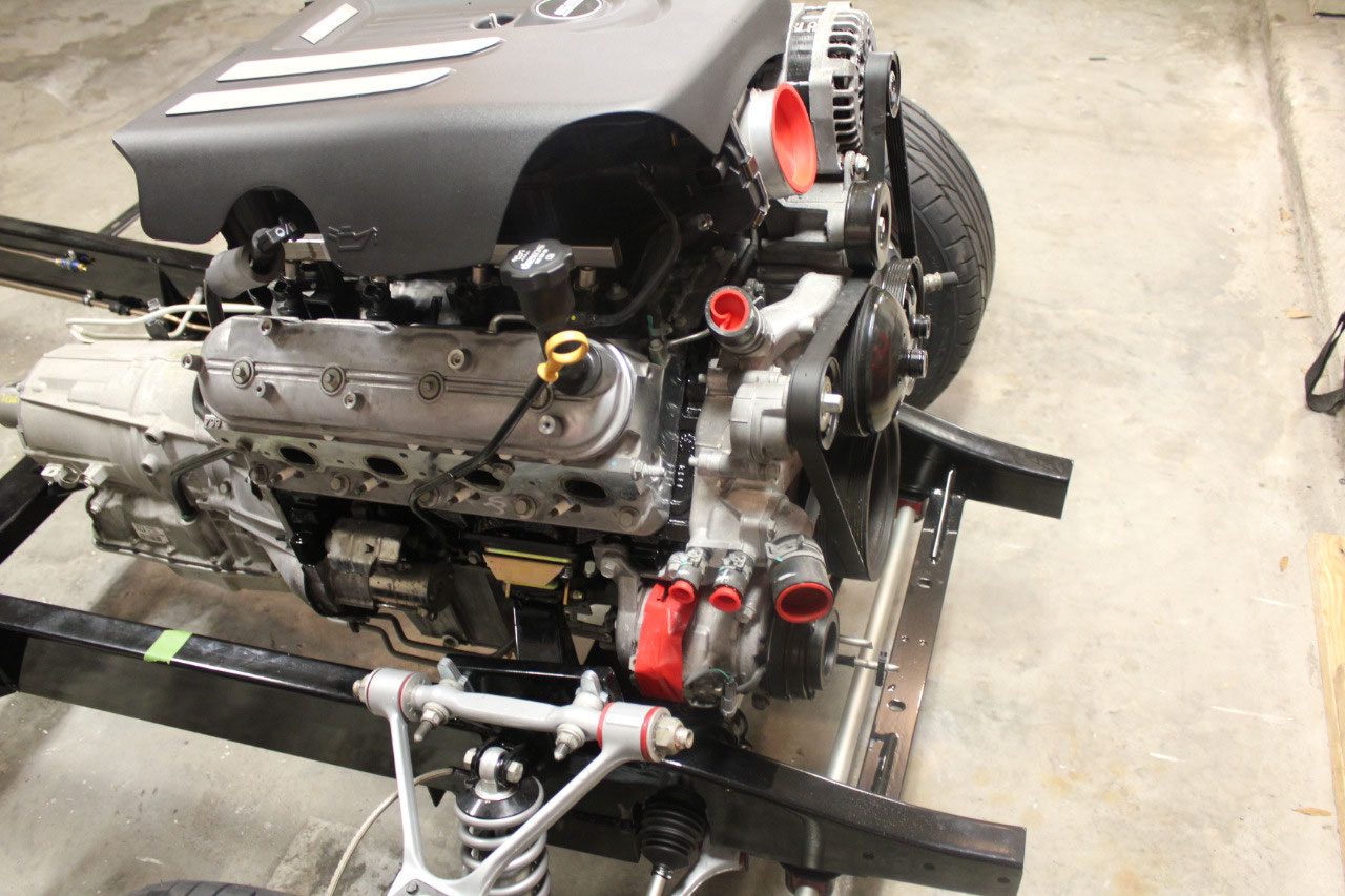
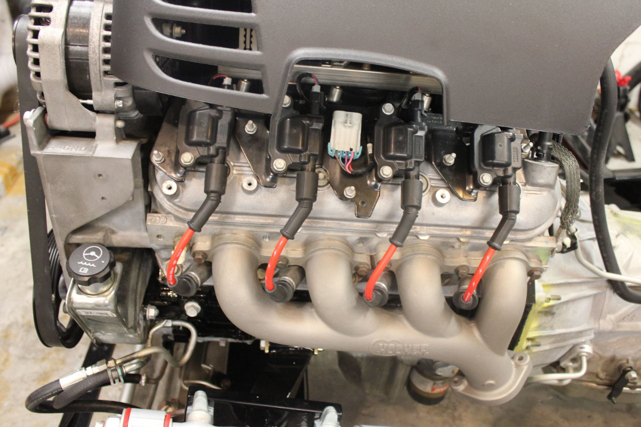
I looked at exhaust clearance, and it looks like the Hooker
exhaust manifolds will work, so I ordered them from Summit Racing. They come in Black, Silver, or Titanium
ceramic coating, or natural, unfinished.
I wanted the silver, which is almost chrome, but there were many bad reviews
about the coating quality on the silver, so I picked the titanium which is a
light gray.
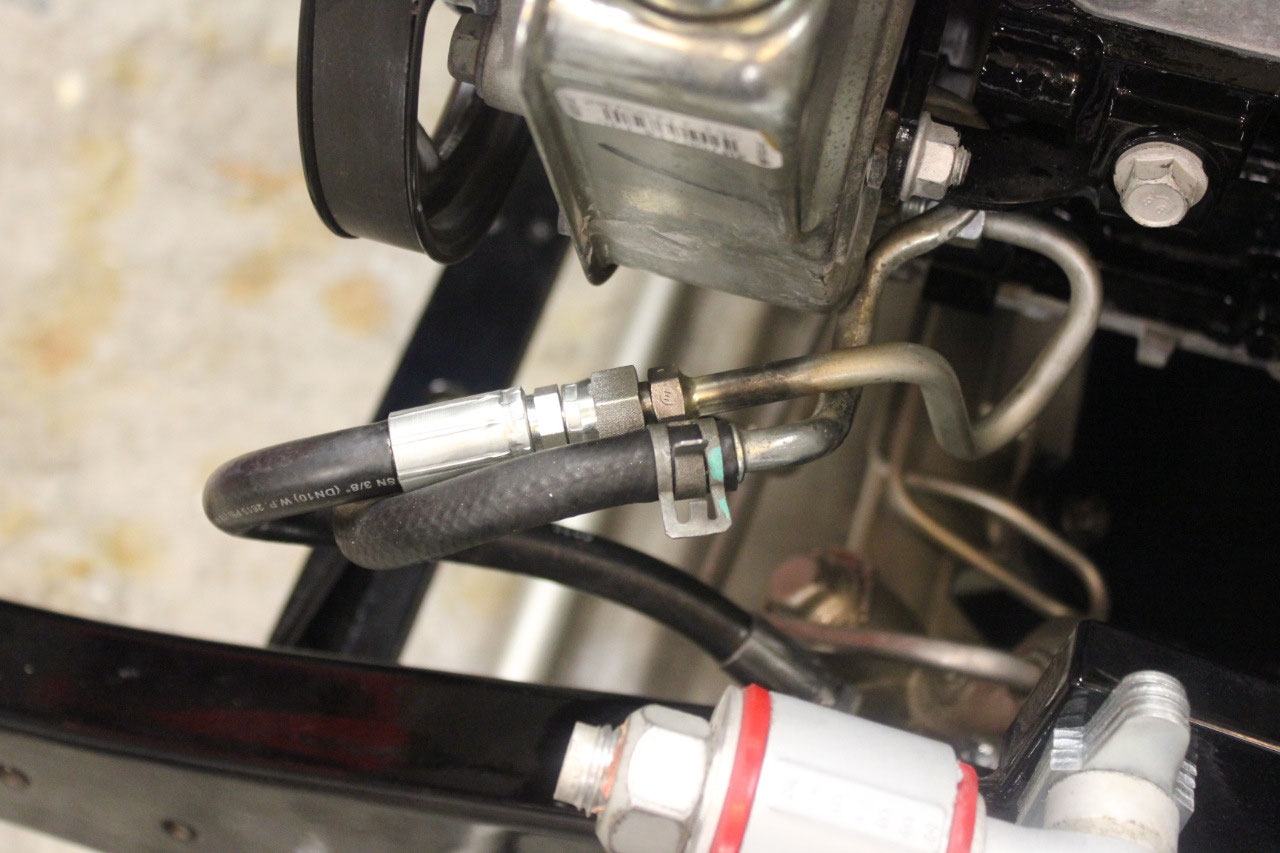
While waiting for the exhaust manifolds, I decided to start
with the power steering hoses. I had a
piece of the original hose from the Tahoe that came with the engine, and I
ordered the Corvette hose which will fit the rack since it was only $20. My hope was that between the two hoses, I
could figure out what a hose should look like.
It turns out it was even easier than I had hoped. I connected the Corvette hose to the rack and
routed it up to where the Tahoe hose came out of the power steering pump. I just market the length and rotation on both
hoses with a sharpie and started looking for a local company to make up a hose.
It turns out there is a place called Amazon Hose only a few
miles away. I brought both hoses with me
and told them what I needed. They can
normally do this while I waited, but he said this was a cut and weld and would
take a little longer. They called me
back at 4:00 and it was ready! It turns
out they only used the ends and installed new hose and couplings. One of the couplings was a swivel, so I could
rotate any way I needed. Total price was
only $27. I installed the hose and it
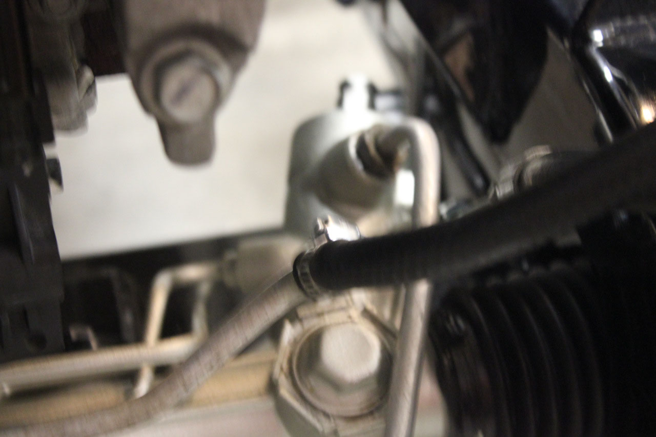
fit perfectly! The power steering return
hose is just a reinforced rubber hose with a couple of clamps. I just picked up some new hose and clamps and
that was the easy part. Power steering
is ready to go!
The exhaust manifolds came in and the quality is
awesome. Bolted them up and they really
tuck in nicely. I already had new
gaskets at the head, but I needed to order studs and gaskets for the flange
end. The manifolds listed the GM part
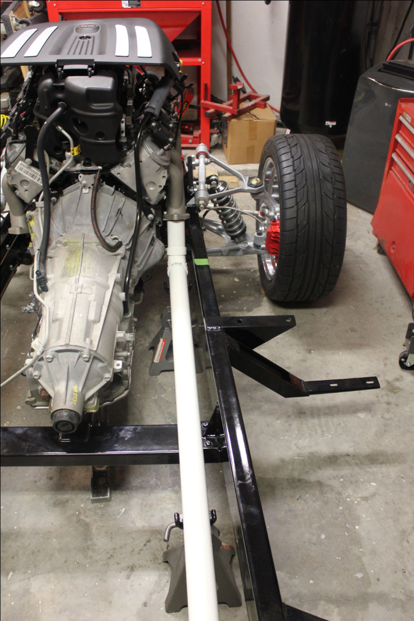
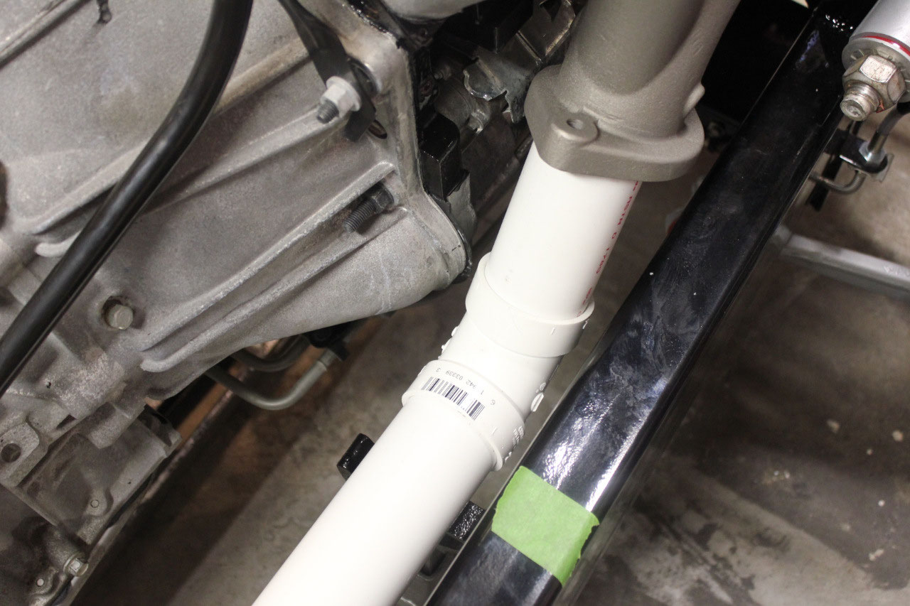
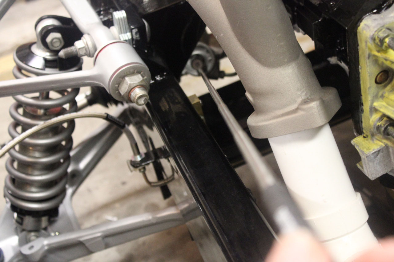
numbers for studs, nuts, and gaskets, so I just ordered them from GM. I also went to Home Depot and got a 60
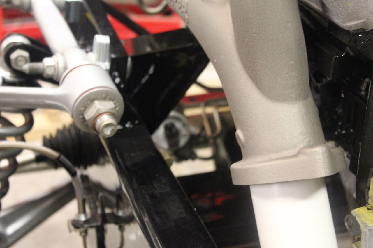
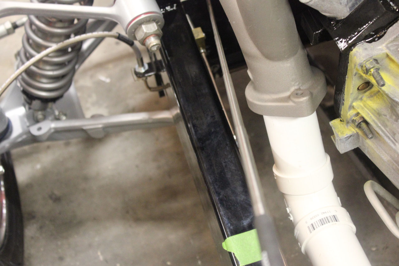
degree PVC elbow and a length of 2” PVC pipe to test fit the exhaust. It looks really good as a straight shot back
from the manifolds after a 60 degree downpipe.
It tucks up above the transmission crossmember within the confines of
the 6” frame rails and looks great.
The 60 degree downpipe is not exactly right, it needs to be
a couple of degrees more, but I planned on using a 6” flex joint on each side
at the end of the downpipe. This should
bend the little bit I need to get the exhaust to line up. I also decided to use an H-Pipe rather than
an X-Pipe as the routing will be easier.
I also decide to stick with stainless tubing as it’s not much more
expensive and is certainly much more durable.
I also ordered some stainless welding wire for my welder, so I will need
to practice stainless welding. Exhaust
pipes are all on order, but the h-pipe is back-ordered until 9/11.
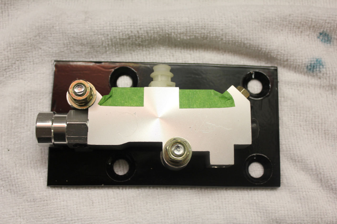
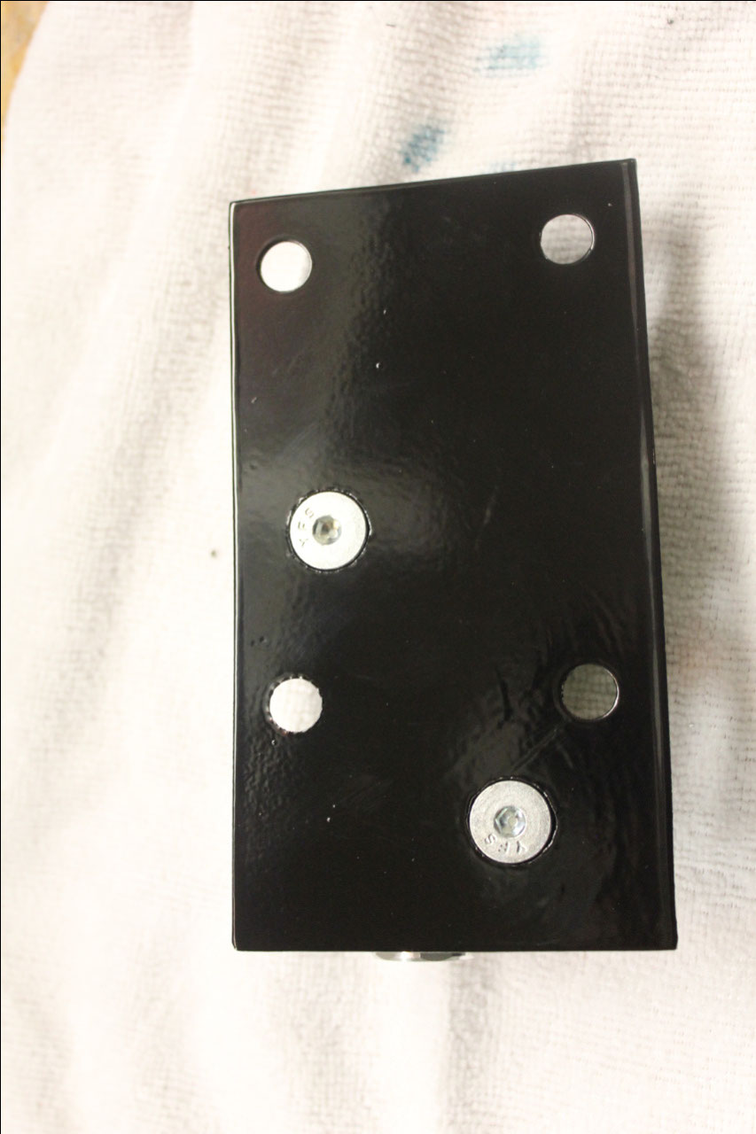
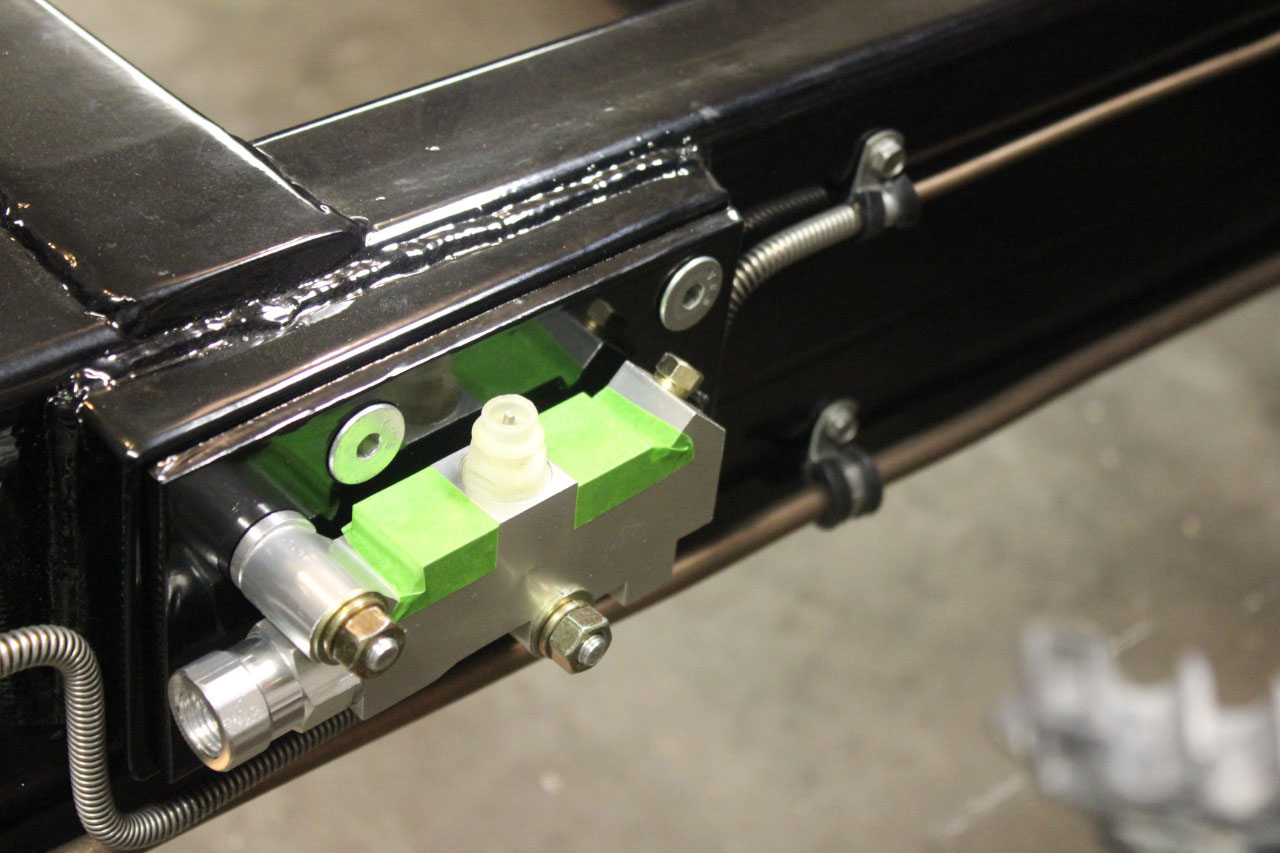
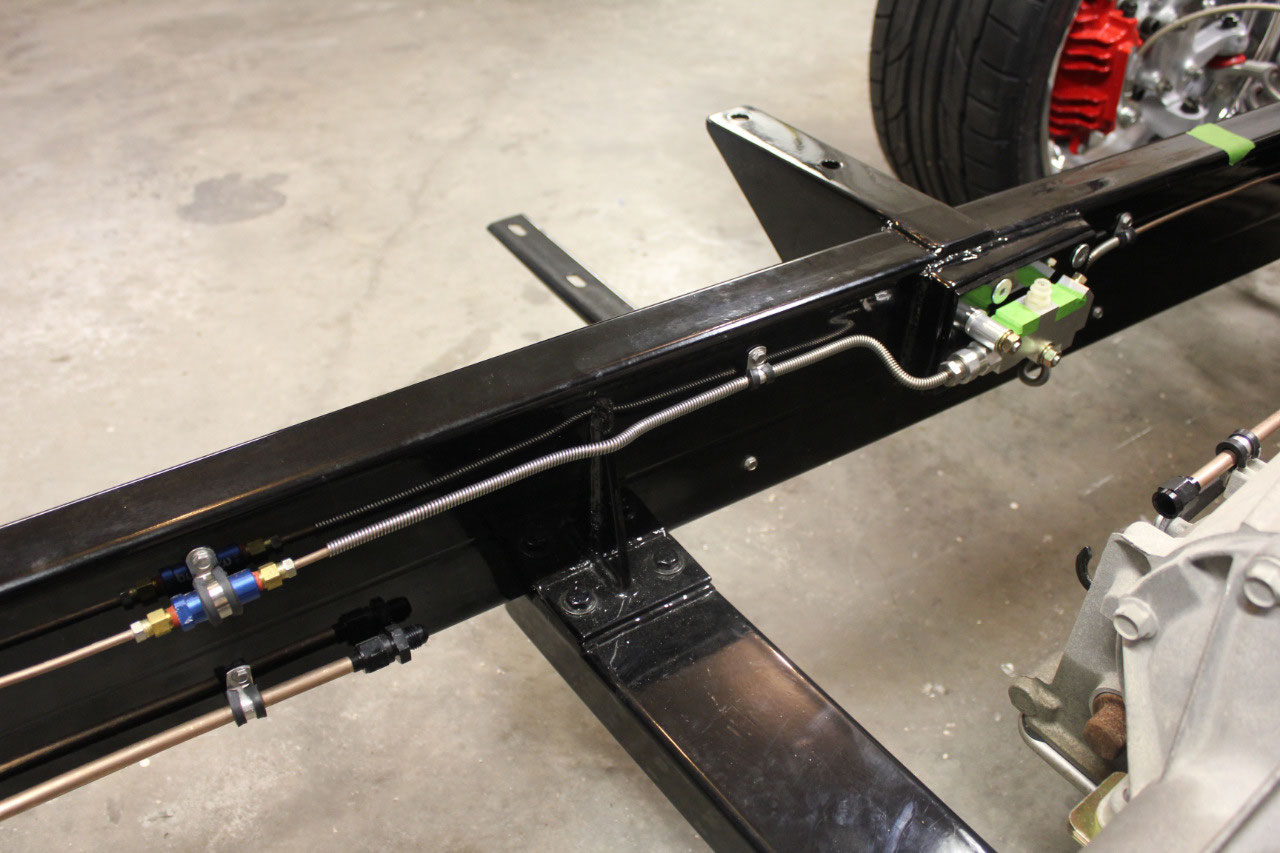
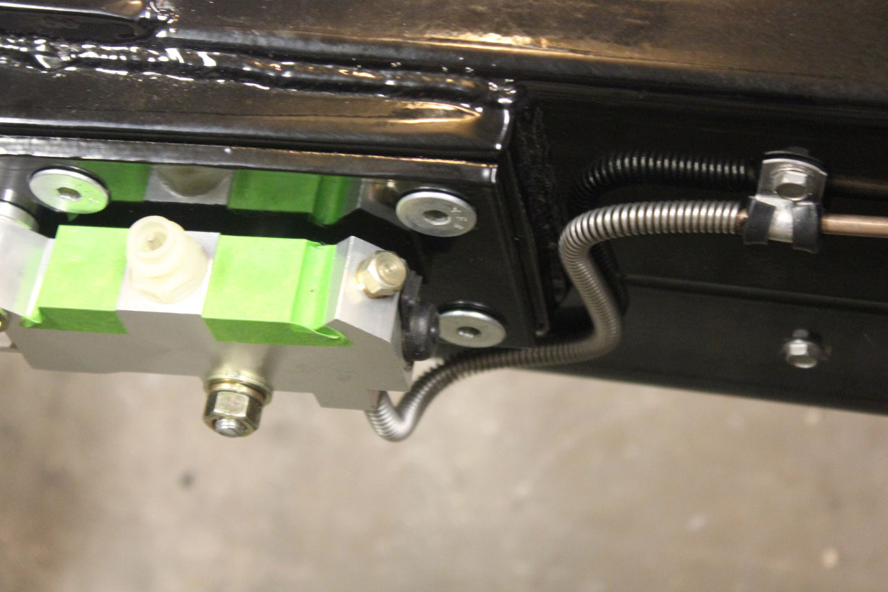
The bolts for the proportioning valve bracket came in today,
so I finished up the countersink on the mounting plate. I had to drag out the powder coating gun, so
I powder coated the proportioning valve bracket and the 2 brackets I made for
the TBSS Engine Cover in black. They
came out great and look very professional.
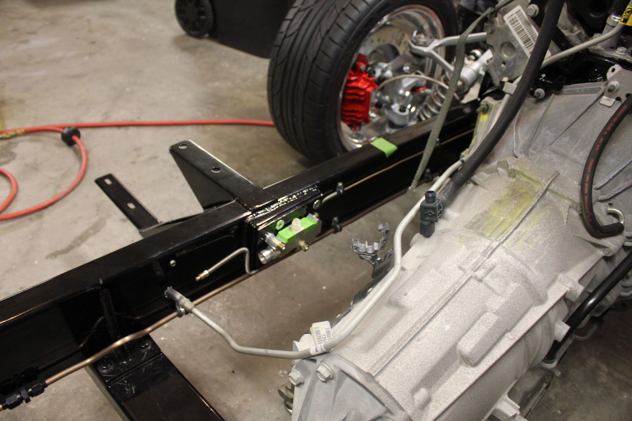
With the proportioning valve mounted, I was able to re-plumb the brake
lines to the new location. When the body
is mounted, I will only need 2 brake lines from the master cylinder to the
proportioning valve. Everything else is
done.
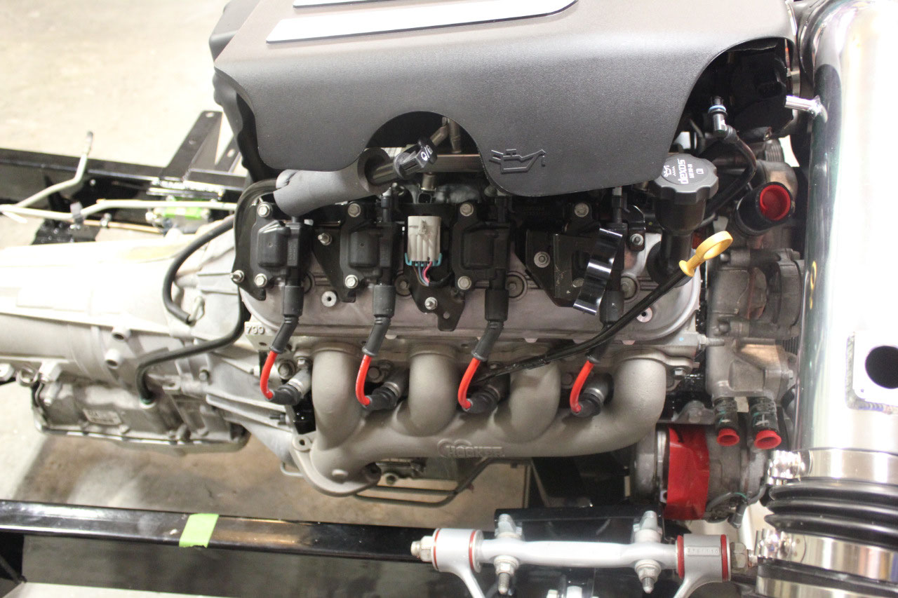
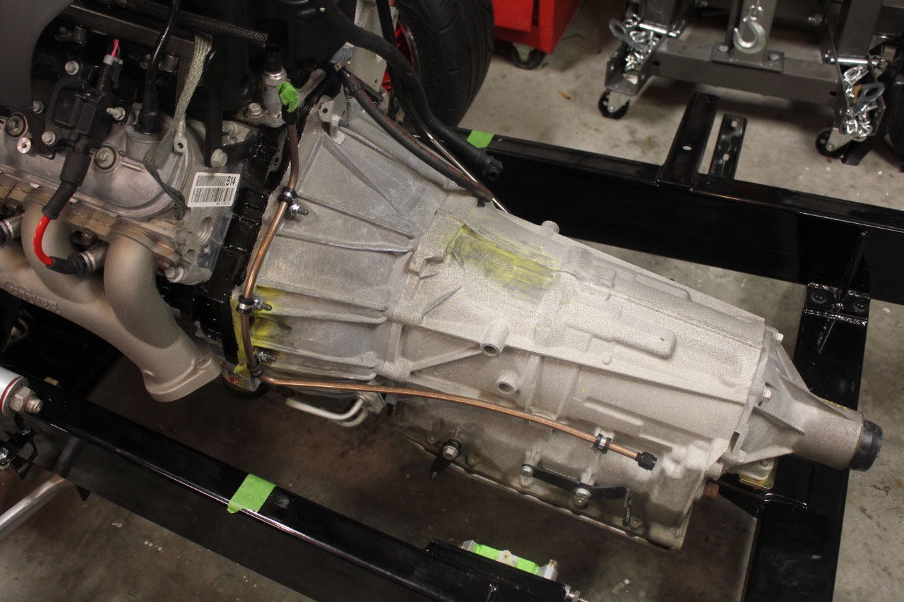
The next project is installing the fuel line from the frame
to the engine fuel rail. I was going to
reuse the steel line that came with the engine, but it was just too difficult
to work with as it was already bent and too hard to rebend. GM uses a flex line at the fuel rail and
another where the fuel line meets the frame.
I’m not sure it’s really necessary at the engine fuel rail, but I
decided to stick with the GM design and do the same. The GM design expects a single exhaust on the
passenger side and the fuel line connects to the frame on the driver’s side. Since I am running dual exhaust, I need to
run the fuel line around the driver’s side exhaust pipe. I was originally going to run the line along
the engine on the driver’s side and head forward in front of the downpipe. This looked too complicated and it looked
easier to run the line similar to the GM design along the side of the transmission. I just dropped it a little lower, out of the
tunnel and below the floor so it should be out of the way.
I had some of the 3/8 conifer fuel line left over from the
frame fuel line so I bent it up to follow the transmission and flared the ends
for -6 AN fittings to connect to a hose at each end. I ordered the fuel hose and fittings from
Summit and decided to use Earl’s products.
I also used a special quick disconnect connector at the engine fuel
rail. The normal quick disconnect uses a
nylon retainer, and this is fine where I used them near the fuel filter. But with the engine heat I used the more
expensive connector with the steel retainer and additional safety clip similar
to the factory connector.
I should be able to finish up the fuel lines this week,
along with a preliminary exhaust mock-up while I wait for the h-pipe. I had hoped to fire up the engine before we
left on a cruise on 9/15 but it looks like I will have to wait until we get
back. In the meantime, I will practice
my stainless welding. Once I have all
the exhaust parts, I hope to cut and fit all the parts and tack weld them in
place. Then I can remove the pipes as an
assembly and finish the welding on the bench.
&l

2025-05-22